Difference between revisions of "Tagger Microscope Mechanical Design"
Senderovich (talk | contribs) m |
Senderovich (talk | contribs) m |
||
| Line 37: | Line 37: | ||
CAD Models | CAD Models | ||
| − | Tagger Microscope (Assembled) [http://www.physics.uconn.edu/~senderovich/GlueX/Tagger/MechDesign/TaggerMicroscope_Assembled.tcw TCW] [http://www.physics.uconn.edu/~senderovich/GlueX/Tagger/MechDesign/TaggerMicroscope_Assembled.dwg DWG] | + | * Tagger Microscope (Assembled) [http://www.physics.uconn.edu/~senderovich/GlueX/Tagger/MechDesign/TaggerMicroscope_Assembled.tcw TCW] [http://www.physics.uconn.edu/~senderovich/GlueX/Tagger/MechDesign/TaggerMicroscope_Assembled.dwg DWG] |
| + | |||
3D views of the assembled Tagger | 3D views of the assembled Tagger | ||
| Line 45: | Line 46: | ||
* [[:media:Tagger3D_4.pdf|Railing support and adjustment motor structure]] | * [[:media:Tagger3D_4.pdf|Railing support and adjustment motor structure]] | ||
* [[:media:Tagger3D_5.pdf|View of "chimney" array for holding fiber waveguides against the photo-sensor/pre-amp PCB]] | * [[:media:Tagger3D_5.pdf|View of "chimney" array for holding fiber waveguides against the photo-sensor/pre-amp PCB]] | ||
| + | |||
Dimensioned Drawings | Dimensioned Drawings | ||
* [[:media:TaggerMicroscope_outerdim.pdf|Outer Dimensions of Tagger Microscope enclosure]] | * [[:media:TaggerMicroscope_outerdim.pdf|Outer Dimensions of Tagger Microscope enclosure]] | ||
| + | |||
== See Also == | == See Also == | ||
* [[:media:StepMotorDriver_R208-manual.pdf|R208 Step Motor Driver]] | * [[:media:StepMotorDriver_R208-manual.pdf|R208 Step Motor Driver]] | ||
Revision as of 23:28, 26 August 2008
Page under construction.
A light-sealed enclosure for the Tagger Microscope is under design. The following requirements have been set forth to constrain it:
- hermetically sealed from light
- if possible, have the ability to work at all usable energies (not just ~9 GeV of GlueX)
- motorized, internal, 3-point adjustment to bring the fiber array plane to appropriate alignment with that of the electrons
- plan for SiPM bias and amplifier board alignment to fiber waveguides (out of the electron plane)
- appropriate room for bending these stiff 2 mm square fibers
- pulser assembly for testing the Tagger without beam
- clearance from all structural elements in front of the scintillators to avoid multiple scattering and bremsstrahlung as well as minimal material downstream of the scintillators
Solutions to these is discussed below.
3-point Fiber Array Adjustment
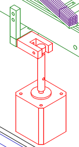
The simplest design for a 3-point adjustable plane on which the fiber modules would be mounted is to have it rest directly on motor shafts positioned vertically. The threaded shafts can lift and lower their respective points by mating them to a threaded through-holes on an elbow assembly that will keep that point fixed but flexible with respect to motion at other points of adjustment.
In this arrangement friction on the thread due to weight of the load is the principle constrain on the choice of motor torque. A conservative approach to this choice would be to allow up to 5 lb of weight per support point, dry-sliding coefficient of friction between pieces of aluminum of 1.4, about 1/8" lever arm of the torque shaft. Torque capability an order of magnitude above that required to overcome the situation of these parameters (14 oz⋅in)
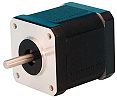
The 83 oz⋅in Lin Engineering 4118L-01 (1.9") Step Motor has been chosen. The unit is close in price to the lower torque models and does not exceed the 2 A limit of the inexpensive driver (meant for lower-end motors).
The combination of these devices have been found easy to control: the driver has simple direction and step resolution selection pins and uses TTL pulses as step commands. The shaft of the motor, which comes smooth (as in the adjacent picture) when bought from distributors. However, it tested to be more than soft enough to machine a flat into it. A cylindrical "sleeve" with threaded outer surface may be inserted over it and tightened against the flat a small headless screw.
Currently Available Drawings
CAD Models
3D views of the assembled Tagger
- Front View
- Side, perspective view from under beam plane
- Fiber module and railing close-up
- Railing support and adjustment motor structure
- View of "chimney" array for holding fiber waveguides against the photo-sensor/pre-amp PCB
Dimensioned Drawings

