Uploads by Senderovich
Jump to navigation
Jump to search
This special page shows all uploaded files.
| Date | Name | Thumbnail | Size | Description | Versions |
|---|---|---|---|---|---|
| 23:13, 5 January 2012 | Xfit hdg.gif (file) |  |
4 KB | State of amplitude fits as of 1/5/2012 | 1 |
| 20:07, 5 January 2012 | Xfit hdg TruthShift.gif (file) |  |
5 KB | State of amplitude fits as of 1/5/2012. True shape curves visibly shifted or skewed with respect to the fitted. | 1 |
| 18:09, 5 January 2012 | Xfit perf-res truth.gif (file) |  |
5 KB | PWA fit with ostensibly good error bars to MC generated 11/2011. Thrown tracks are used after the event selection based on reconstructed data analysis. | 1 |
| 18:08, 5 January 2012 | Xfit perf-res matchedtracks.gif (file) |  |
5 KB | PWA fit with ostensibly good error bars to MC generated 11/2011. Thrown tracks matched to reconstructed ones are used after analysis/cuts on reconstruction data. | 1 |
| 18:07, 5 January 2012 | Xfit hdg goodErr.gif (file) |  |
4 KB | PWA fit with ostensibly good error bars to MC generated 11/2011 | 1 |
| 18:06, 23 March 2011 | Beamtest-jlab dwssap.jpg (file) |  |
26 KB | 1 | |
| 17:44, 22 March 2011 | Beamtest dwssap.jpg (file) |  |
35 KB | 1 | |
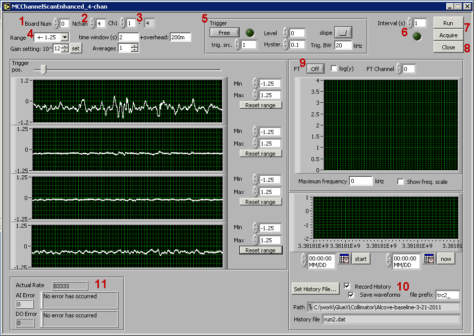
| 02:21, 22 March 2011 | MMChanScan SSchecklist.png (file) |  |
36 KB | Screen shot of the DAQ Labview VI for reading out the active collimator with annotations for reference with a run shift checklist | 1 |
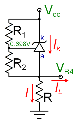
| 16:17, 30 September 2010 | VrefSum.png (file) |  |
5 KB | Voltage reference circuit for the SiPM amplifier summing stage. This one is referenced to the supply voltage as opposed to ground. | 2 |
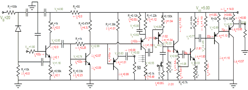
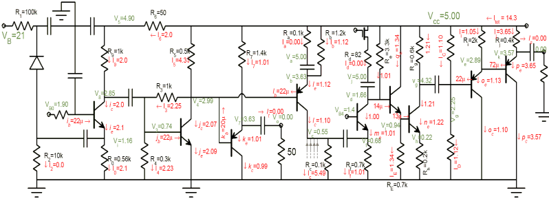
| 05:07, 21 September 2010 | AmpCircuit v7 DC.png (file) |  |
27 KB | SiPM Amplifier circuit with DC levels | 1 |
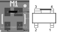
| 16:20, 31 March 2010 | AmpBoard FETorient.png (file) |  |
2 KB | Amplifier board summing circuit gain switch (FET) placement orientation diagram | 1 |
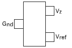
| 16:10, 31 March 2010 | AmpBoard Vref.png (file) |  |
572 bytes | Voltage reference pinout for amplifier board | 1 |
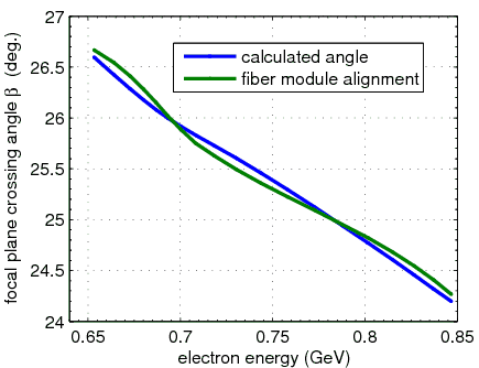
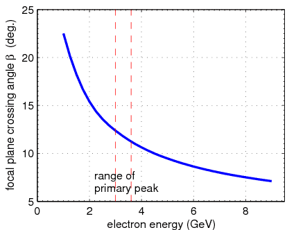
| 19:09, 12 November 2009 | CrossingAngle lowE.png (file) |  |
8 KB | Crossing angle vs energy along the focal plane, focusing on the low-energy end. | 1 |
| 19:08, 12 November 2009 | CrossingAngle.png (file) |  |
6 KB | electron crossing angle vs. energy along the focal plane | 1 |
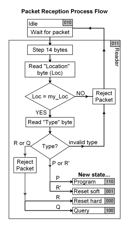
| 06:26, 5 November 2009 | ReaderProcess.png (file) |  |
20 KB | Reader logic scheme | 2 |
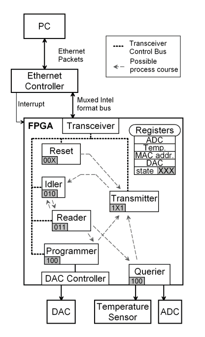
| 06:12, 5 November 2009 | DigBoardScheme.png (file) |  |
21 KB | Operation scheme of the FPGA firmware in terms of the Eth. Ctrl. communication modules | 3 |
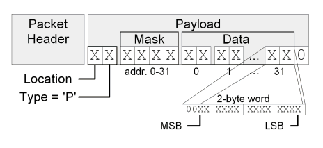
| 04:50, 5 November 2009 | P-packetPayload.png (file) |  |
9 KB | P-packet (programming) format diagram | 2 |
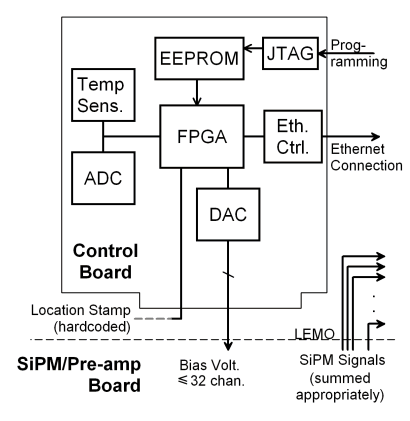
| 05:21, 29 October 2009 | ControlBoard.png (file) |  |
12 KB | Schematic illustration of the signal flow on the control board | 1 |
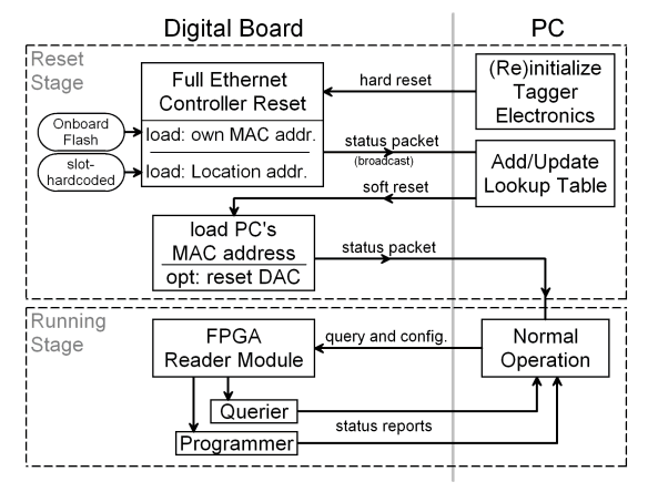
| 21:06, 28 October 2009 | OperationCourse.png (file) |  |
23 KB | Diagram showing the startup and steady operation scheme in terms of the exchange between Control Board and the controlling PC | 2 |
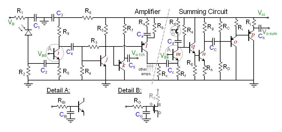
| 19:38, 5 October 2009 | AmpVis v6 DC.png (file) |  |
25 KB | DC levels in the SiPM amplifier (final version) | 3 |
| 01:29, 16 September 2009 | AmpVis v6 DC labels.png (file) |  |
17 KB | 3 | |
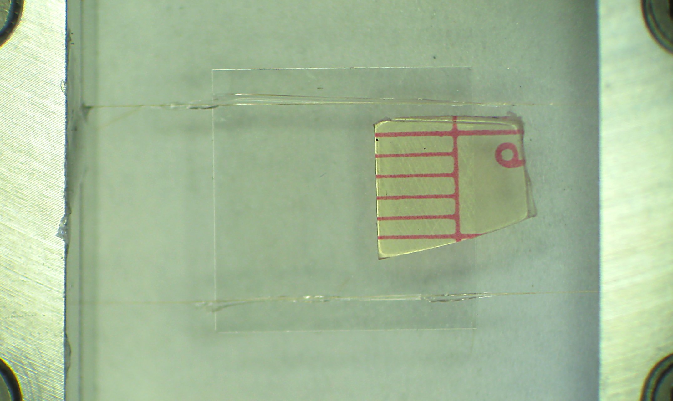
| 04:21, 28 April 2009 | DiaGlued.jpg (file) |  |
153 KB | Diamond glued to 20um wires. | 1 |
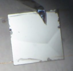
| 04:19, 28 April 2009 | Dia Yboundary.jpg (file) |  |
6 KB | Strange artifact on 300um diamond: Y-shaped "boundaries" | 1 |
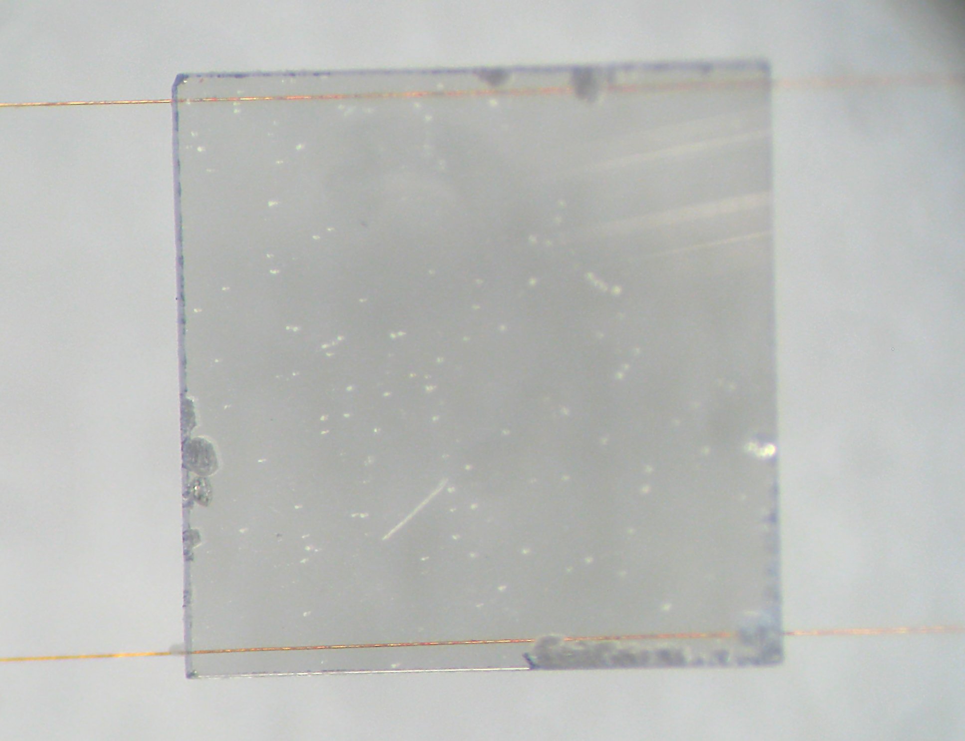
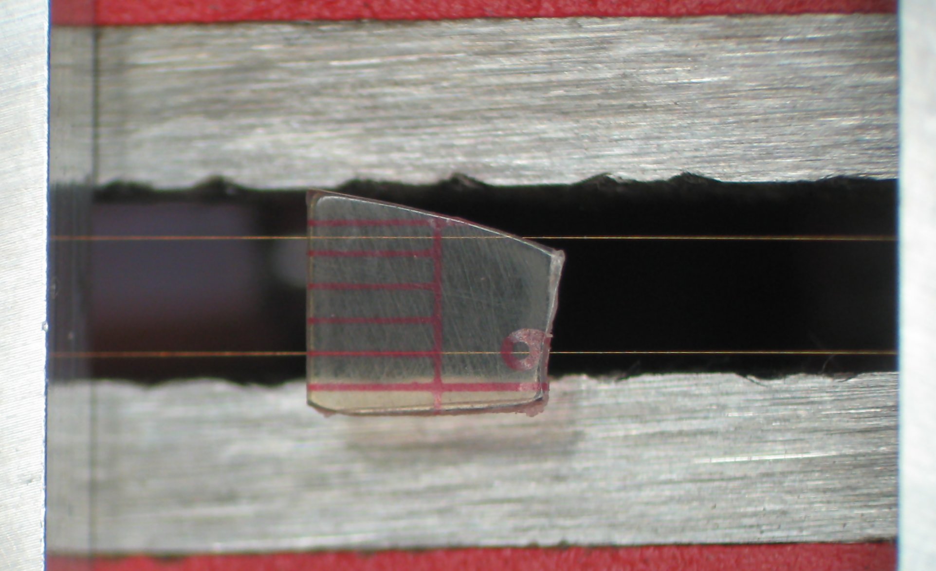
| 04:18, 28 April 2009 | GlueTest glass.jpg (file) |  |
226 KB | Glass piece glued to 20um tungsten wires for practice. | 1 |
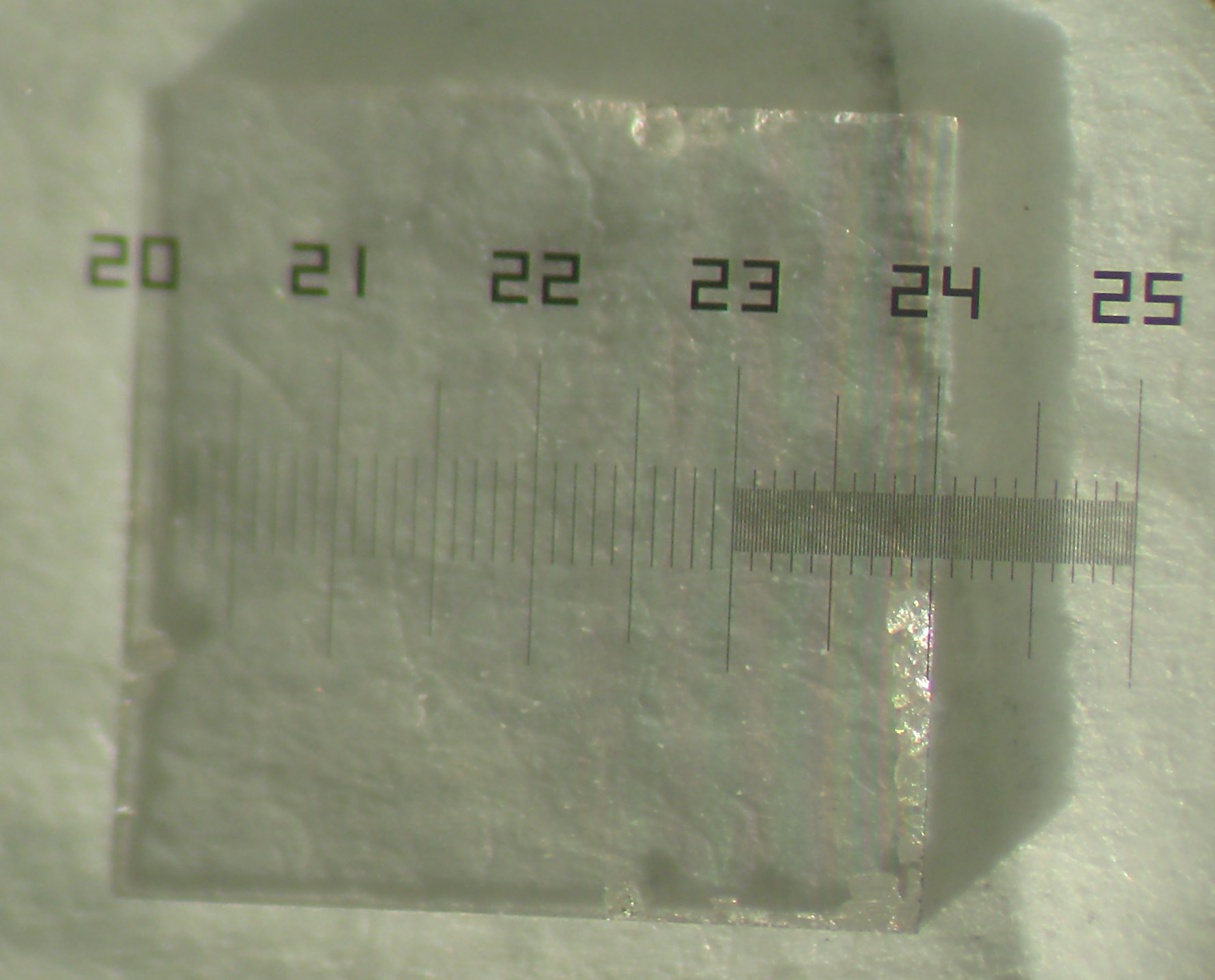
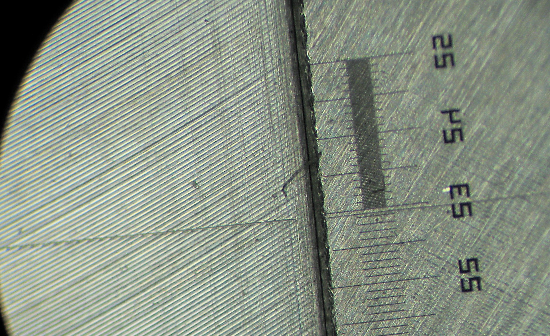
| 04:18, 28 April 2009 | DiaSize.jpg (file) |  |
179 KB | Photo of 300um thick diamond from BNL. (Shown with scale) | 1 |
| 04:18, 28 April 2009 | Wires 6-32.jpg (file) |  |
211 KB | Stretched wires spaced by the shank of 6-32 screw. | 1 |
| 14:49, 23 April 2009 | MBWireMarks.jpg (file) |  |
738 KB | Wire marks left on clamp from 20um wire. | 1 |
| 14:48, 23 April 2009 | WireStretchTests.jpg (file) |  |
451 KB | Picture of grooves embossed by the 20um tungsten wire upon compression. | 1 |
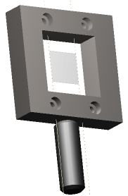
| 05:18, 15 April 2009 | DiaMountBracket.png (file) |  |
14 KB | 3D view of the diamond holder for CHESS measurements (complete with shaft) | 3 |
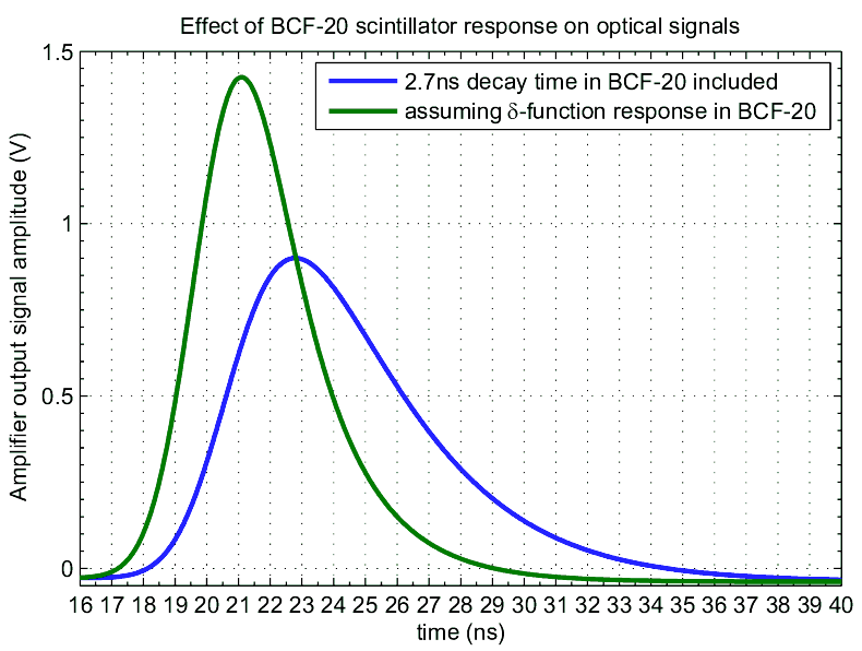
| 20:31, 12 February 2009 | Scint Amp resp.png (file) |  |
20 KB | Amplifier signal shape taking into account scintillator response | 1 |
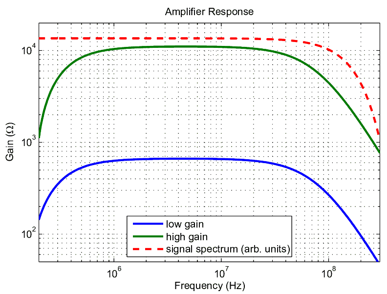
| 07:34, 5 February 2009 | AmpResp.png (file) |  |
17 KB | Amplifier's spectral response. | 1 |
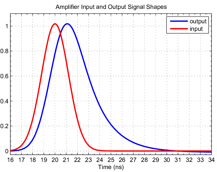
| 06:25, 5 February 2009 | Amp In-Out-Pulses.png (file) |  |
17 KB | Comparison of input and output pulses for the SiPM amplifer. | 1 |
| 18:24, 4 February 2009 | TaggerBoards.png (file) |  |
14 KB | Cartoon-like schematic of the microscope components and the signal flow. | 5 |
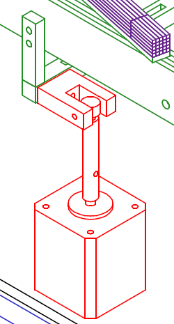
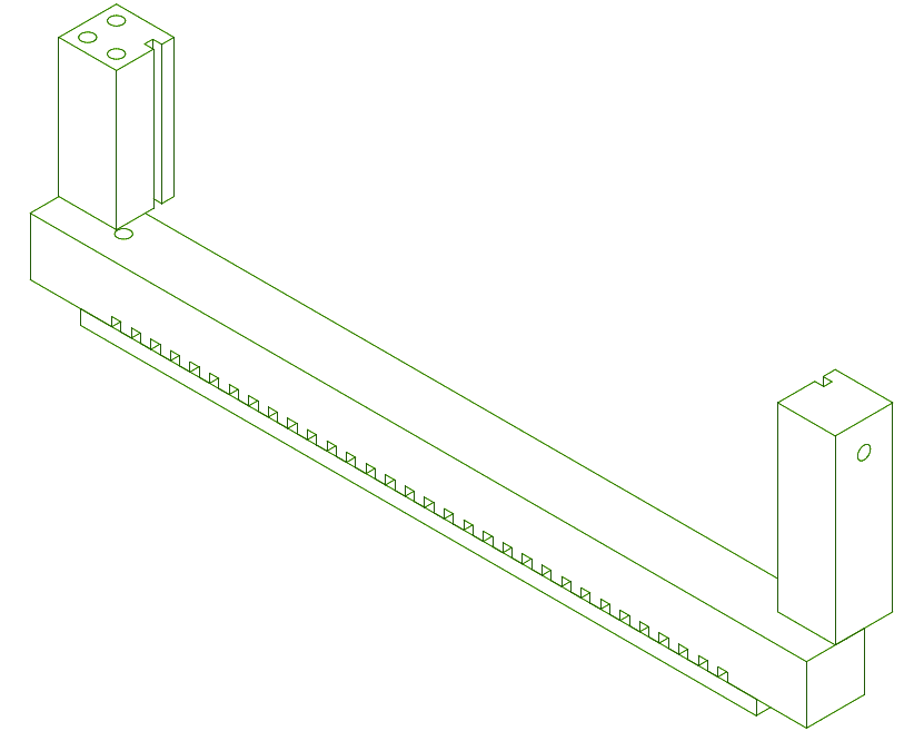
| 05:01, 3 October 2008 | MotorSupport closeup.png (file) |  |
21 KB | 2 | |
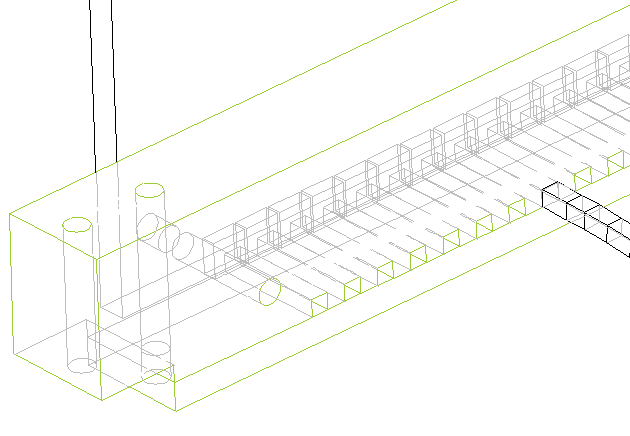
| 17:02, 8 September 2008 | Chimney.png (file) |  |
9 KB | 1 | |
| 01:19, 27 August 2008 | Chimney-AmpBoard.png (file) |  |
10 KB | 1 | |
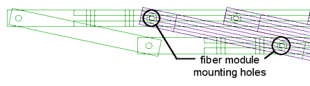
| 00:18, 27 August 2008 | FiberModuleMounting.png (file) |  |
5 KB | 1 | |
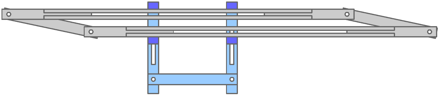
| 23:53, 26 August 2008 | ParallelRailingConcept.png (file) | 4 KB | Drawing of the concept of parallel railing for fiber module adjustment to the electron crossing angle | 1 | |
| 23:26, 26 August 2008 | TaggerMicroscope outerdim.pdf (file) | 304 KB | 1 | ||
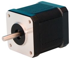
| 23:09, 26 August 2008 | LinEng 4118-01 StepMotor.jpg (file) |  |
7 KB | 1 | |
| 22:31, 26 August 2008 | StepMotorDriver R208-manual.pdf (file) | 254 KB | 1 | ||
| 19:02, 26 August 2008 | Tagger3D 5.pdf (file) | 43 KB | 1 | ||
| 19:02, 26 August 2008 | Tagger3D 4.pdf (file) | 7 KB | 1 | ||
| 19:02, 26 August 2008 | Tagger3D 3.pdf (file) | 7 KB | 1 | ||
| 19:02, 26 August 2008 | Tagger3D 2.pdf (file) | 53 KB | 1 | ||
| 19:02, 26 August 2008 | Tagger3D 1.pdf (file) | 36 KB | 1 | ||
| 18:11, 26 August 2008 | TaggerFocalPlane ChannelPlan.png (file) | 2 KB | Tagger Microscope channel plan along the focal plane | 1 | |
| 18:10, 26 August 2008 | TaggerFocalPlane ChennelPlan.png (file) | 2 KB | Tagger Microscope channel plan along the focal plane | 1 | |
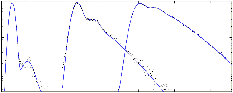
| 17:19, 28 July 2008 | HPD 3dist.png (file) |  |
9 KB | Three spectra collected by the HPD at very different light levels showing different contributions from the secondaries. | 1 |
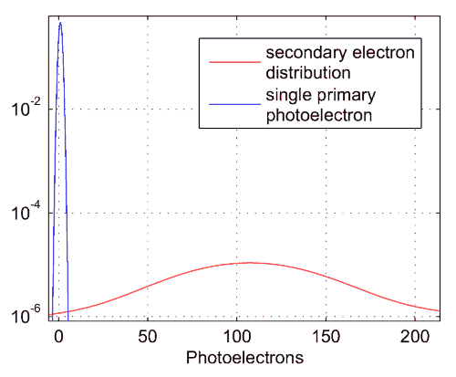
| 19:01, 16 July 2008 | HPD OnePEdist.png (file) |  |
6 KB | Distributions of primary and secondary photoelectron signals (noise included) for one incident primary photoelectron. | 1 |