Uploads by Nettleton
Jump to navigation
Jump to search
This special page shows all uploaded files.
| Date | Name | Thumbnail | Size | Description | Versions |
|---|---|---|---|---|---|
| 18:18, 30 October 2008 | Wgclamp.JPG (file) |  |
1.31 MB | 1 | |
| 18:17, 30 October 2008 | Chimneyclamped.JPG (file) |  |
1.51 MB | 1 | |
| 18:16, 30 October 2008 | Wgandscint1.JPG (file) |  |
1.11 MB | 1 | |
| 18:16, 30 October 2008 | Wgandscint.JPG (file) |  |
1.37 MB | 1 | |
| 22:35, 27 October 2008 | Chimneyscint1.JPG (file) |  |
1.38 MB | 1 | |
| 22:31, 27 October 2008 | Glueremovalstarted1.JPG (file) |  |
817 KB | 1 | |
| 22:29, 27 October 2008 | Glueremovalfinished.JPG (file) |  |
565 KB | 1 | |
| 22:28, 27 October 2008 | Gluebump.JPG (file) |  |
964 KB | 1 | |
| 22:27, 27 October 2008 | Chimneywg1.JPG (file) |  |
1.51 MB | 1 | |
| 22:26, 27 October 2008 | Chimneywg.JPG (file) |  |
1.44 MB | 1 | |
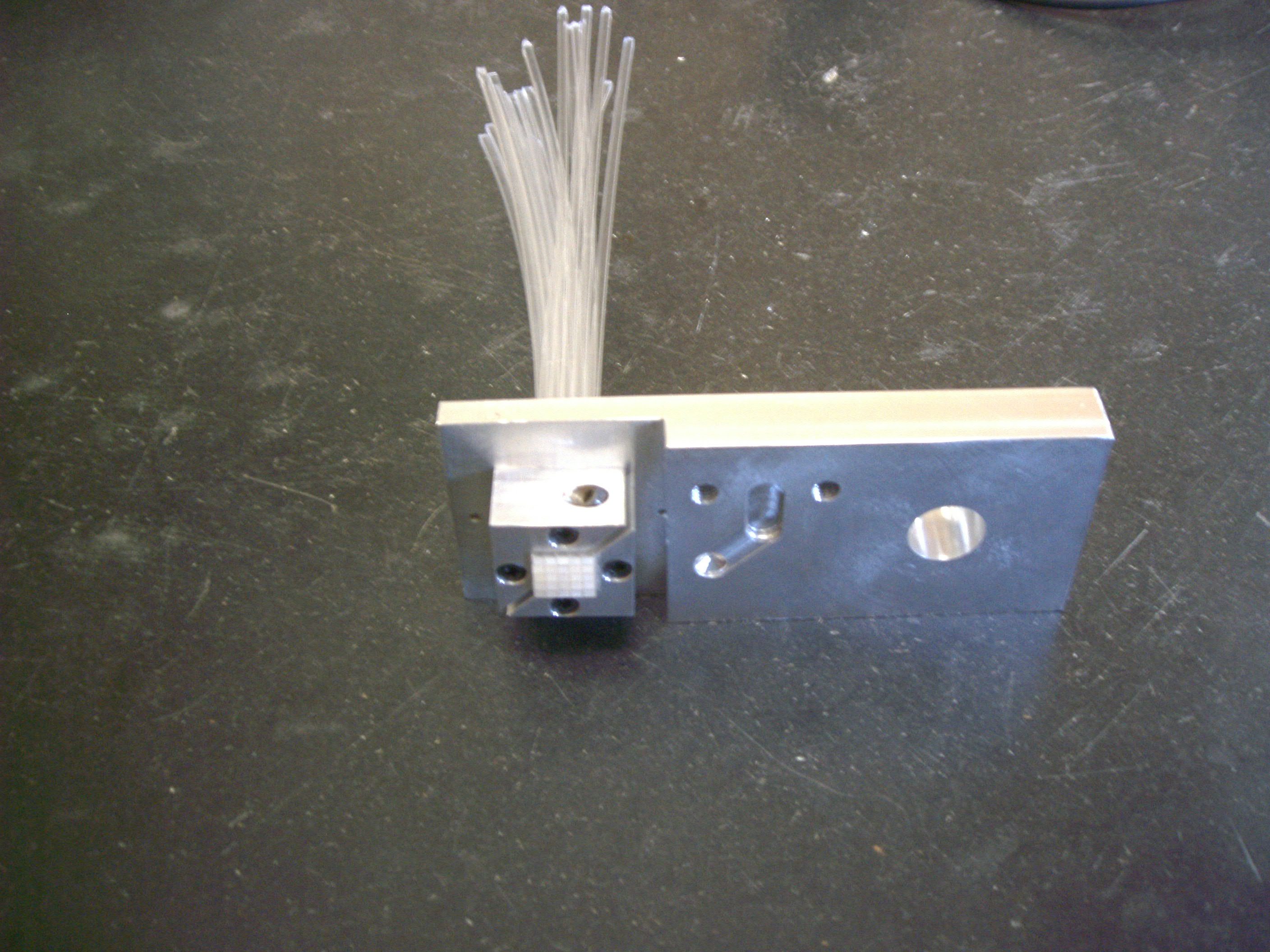
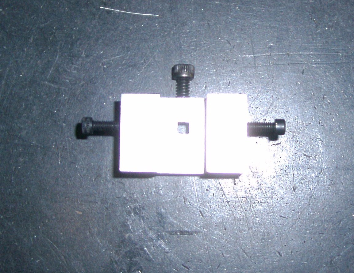
| 18:27, 16 July 2008 | Fibersinangleclamp.JPG (file) |  |
1.05 MB | 1 | |
| 17:53, 16 July 2008 | Recessed inner afterflycut.jpg (file) |  |
135 KB | 1 | |
| 17:50, 16 July 2008 | Scratches afterflycut.jpg (file) |  |
131 KB | 1 | |
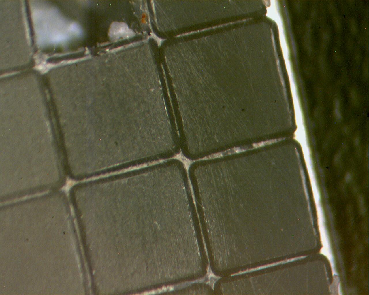
| 17:47, 16 July 2008 | Fiberbundle stripped zoomout.jpg (file) |  |
100 KB | We see here that the fibers on the outer part of the bundle have some of there cladding stripped away. The amount of cladding stripped is not consistent but it is clear that the majority of fibers do have a noticeable amount of cladding removed. | 1 |
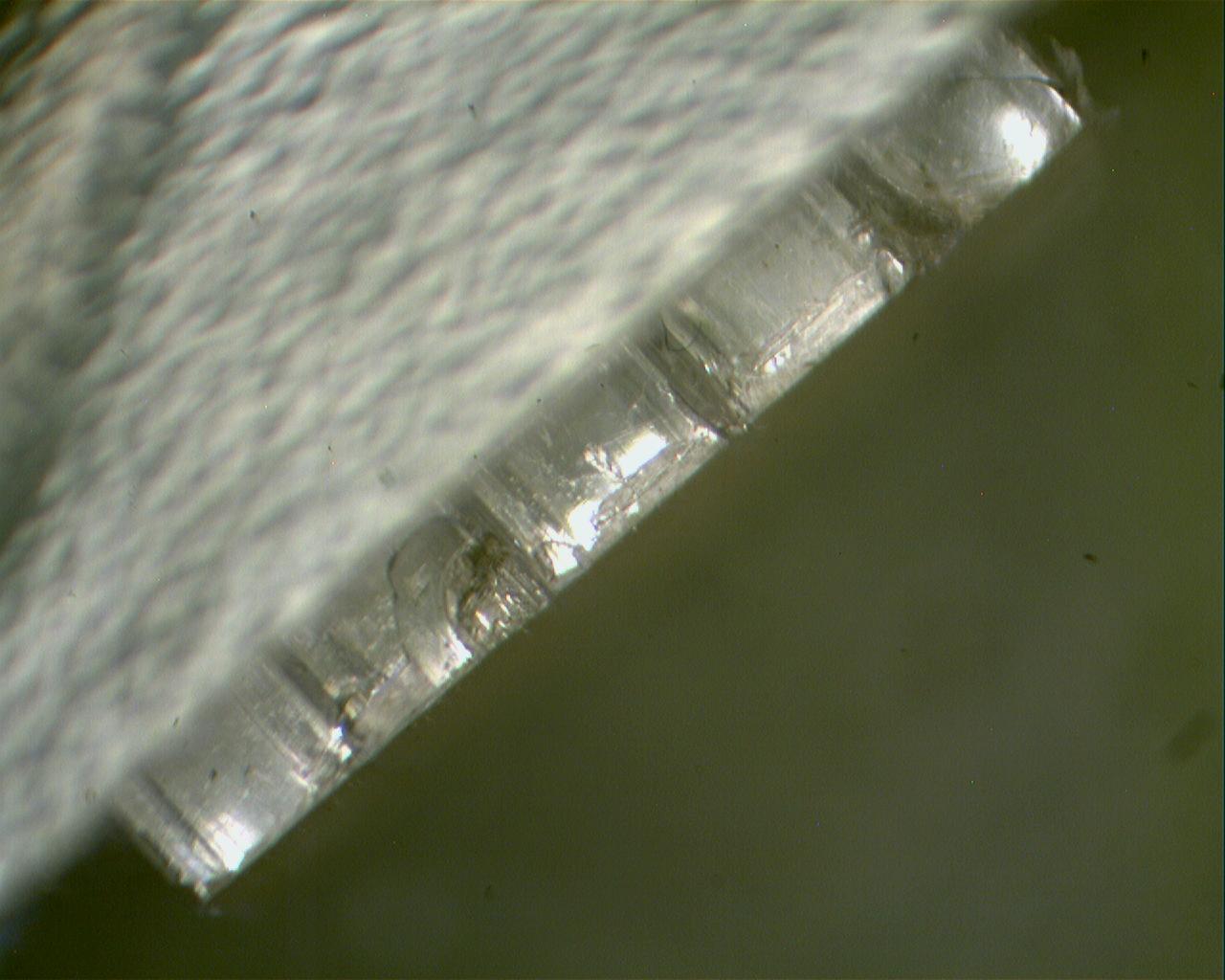
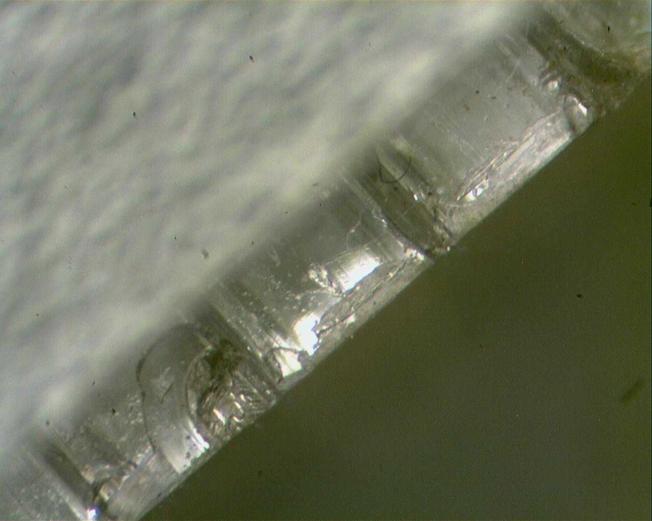
| 17:39, 16 July 2008 | Fiberbundle stripped.jpg (file) |  |
111 KB | Here we see the outer fibers in the angle clamp after being cut with the carbide bit fly cutter at 1500 rpms. | 1 |
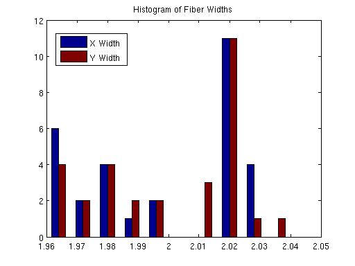
| 17:26, 3 July 2008 | Xyfibersizehist.jpg (file) |  |
19 KB | 1 | |
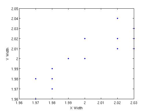
| 17:25, 3 July 2008 | X vs yfibersizeplot.jpg (file) |  |
12 KB | 1 | |
| 20:57, 13 May 2008 | ThermFinger.jpg (file) |  |
50 KB | 2 | |
| 20:20, 13 May 2008 | Plug.jpg (file) |  |
61 KB | 1 | |
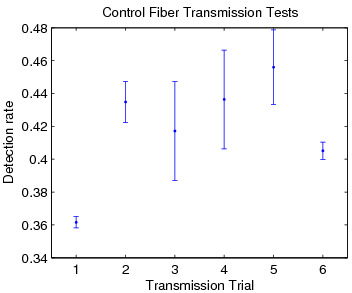
| 20:02, 13 May 2008 | CtrlTrTests.png (file) |  |
10 KB | 1 | |
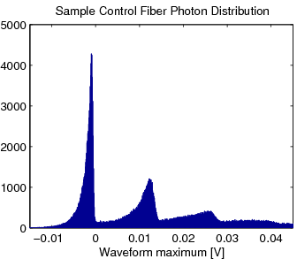
| 20:01, 13 May 2008 | CtrlPhotonDist.png (file) |  |
12 KB | 1 | |
| 16:21, 5 March 2008 | Top.JPG (file) |  |
402 KB | 1 | |
| 16:21, 5 March 2008 | Front.JPG (file) |  |
249 KB | 1 | |
| 16:20, 5 March 2008 | Protochimney submit.jpg (file) |  |
56 KB | 1 | |
| 16:20, 5 March 2008 | Back.JPG (file) |  |
203 KB | 1 | |
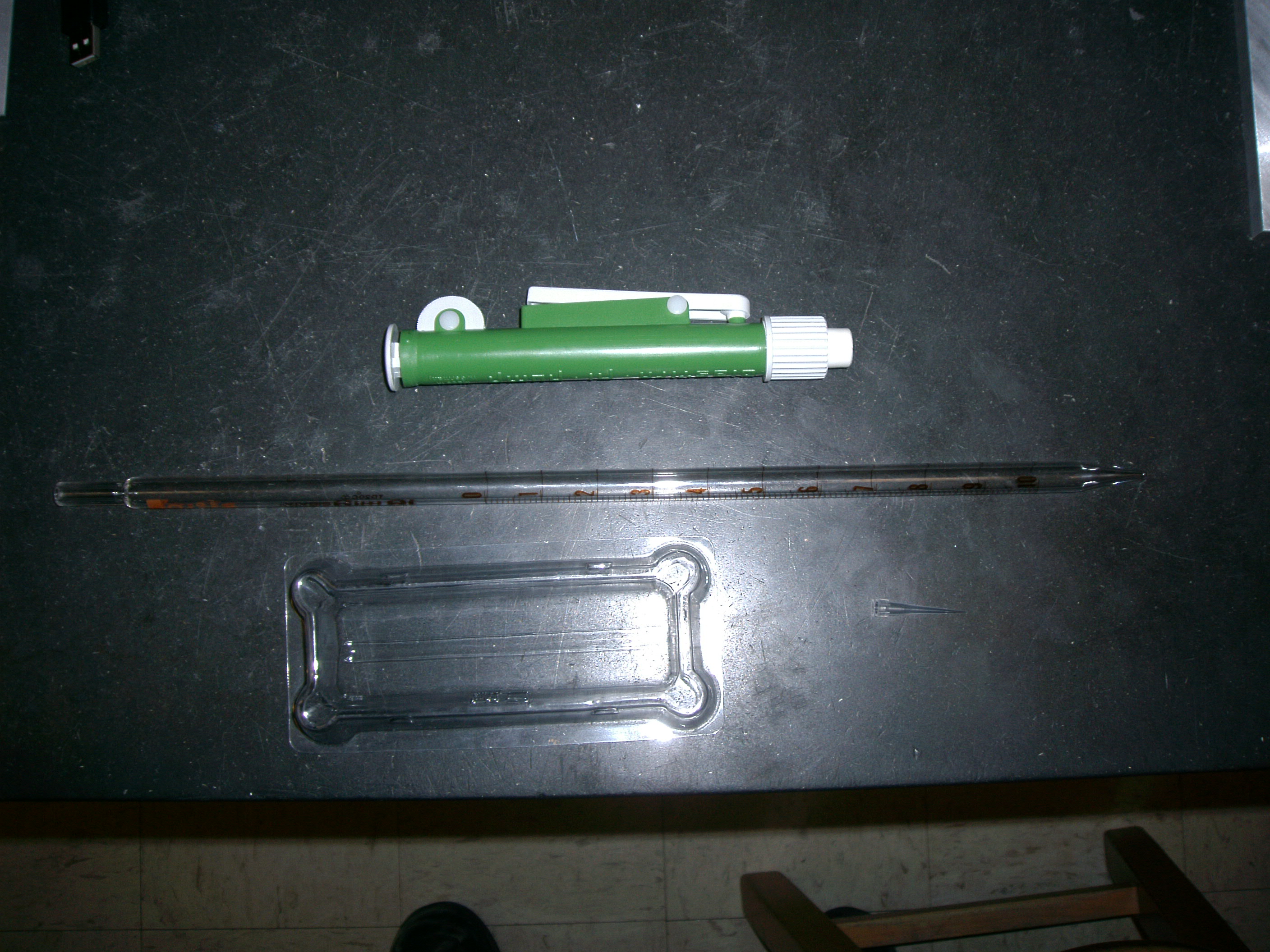
| 16:30, 19 December 2007 | Pipette equip.JPG (file) |  |
1.5 MB | The upper most item, green in color, is called the "dispensing pump," below that is the pipette. The lower left image is the mixing basin, the lower right is the pipette tip. | 1 |
| 16:13, 19 December 2007 | Glued Fibers.JPG (file) |  |
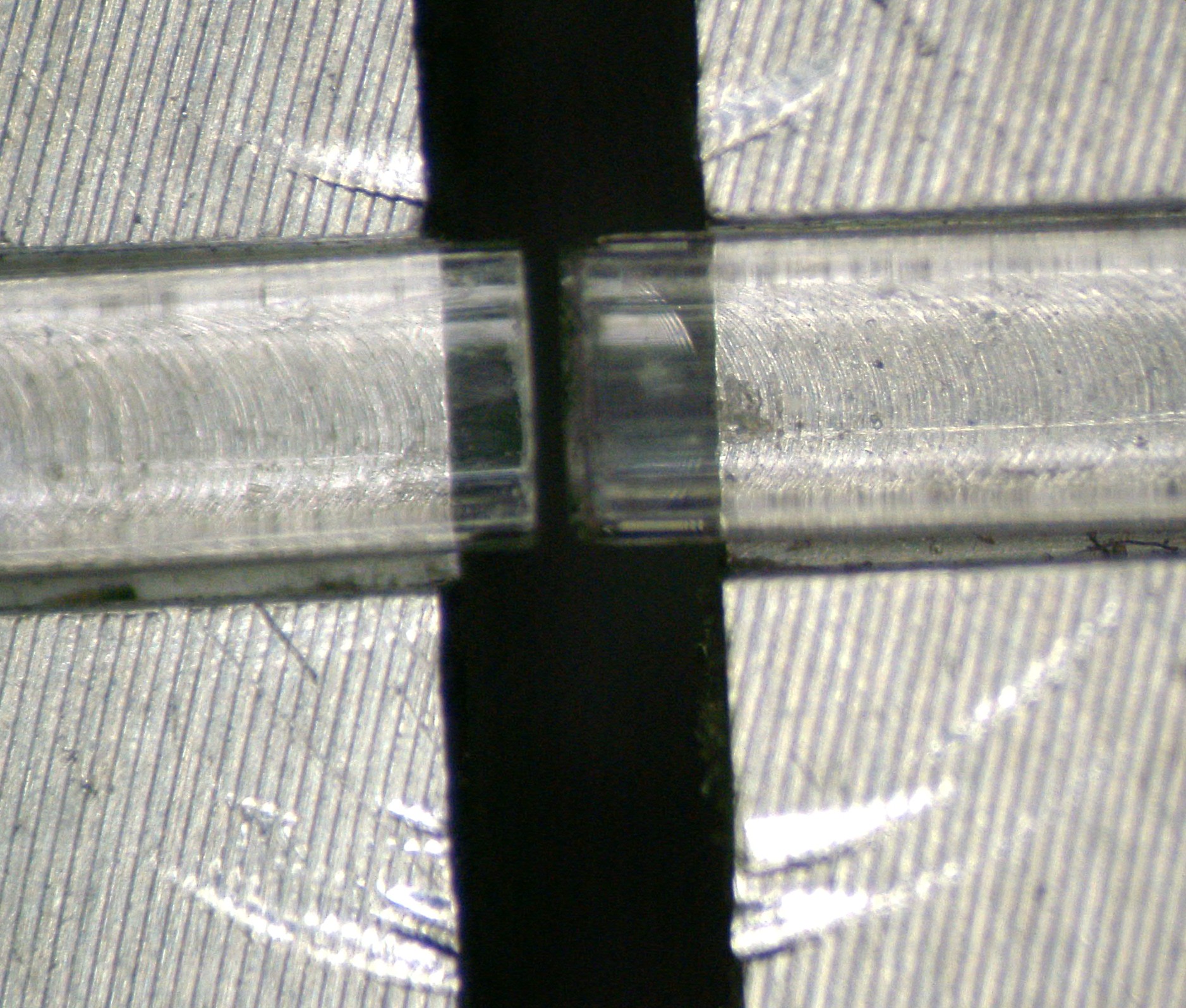
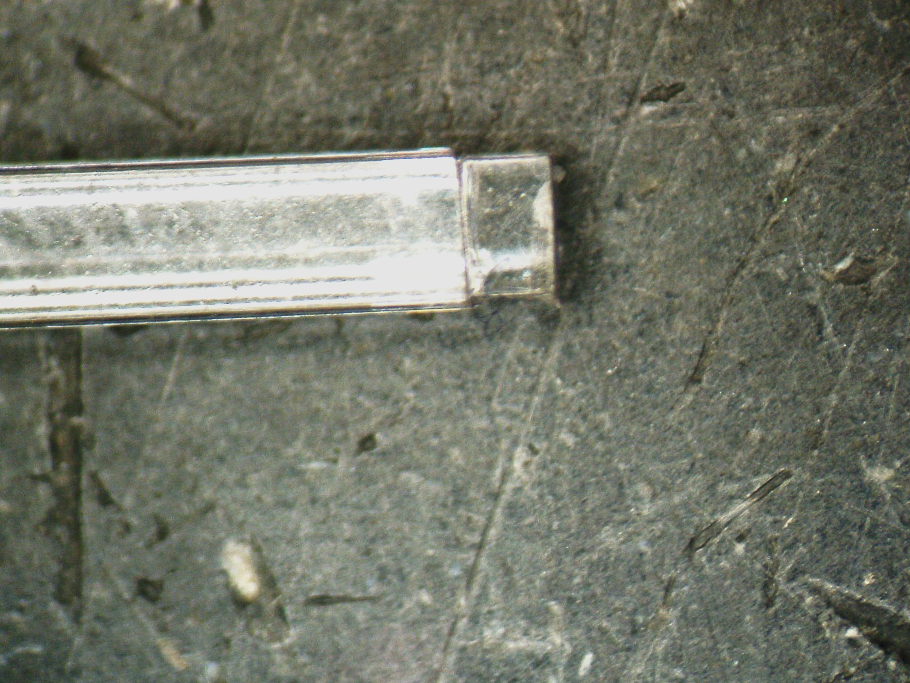
638 KB | Notice here that the fibers are not actually touching, but the epoxy bridges the gap between the two fiber. | 1 |
| 13:46, 19 December 2007 | Setup Noepoxy.JPG (file) |  |
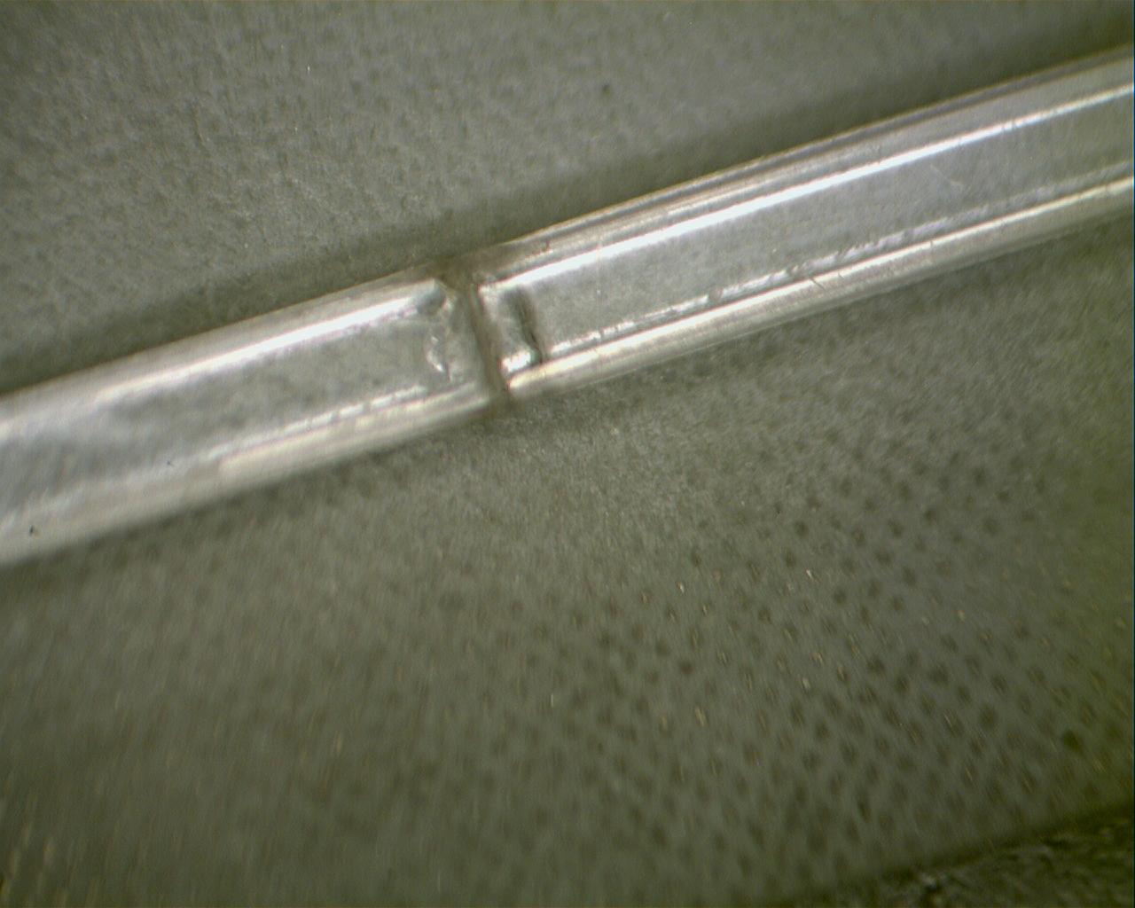
640 KB | In this photo we see the two fibers lying in the groove of the work stand cutguide, before applying the epoxy. Also notice the ends of the fibers, they are the result of polishing down the fiber after stripping the cladding. | 1 |
| 13:30, 19 December 2007 | Stripped Cladding.JPG (file) |  |
575 KB | Here we see the removed outer cladding. For instructions on how to accomplish this, see Cleaving Technique 2. | 1 |
| 22:50, 24 October 2007 | Gluetest1.jpg (file) |  |
112 KB | 1 | |
| 17:57, 10 October 2007 | Bent.jpg (file) |  |
142 KB | The "tiger stripe" marks on the fiber appear when the fiber is bent past its minimum bending radius. | 1 |
| 17:51, 10 October 2007 | Emery.jpg (file) |  |
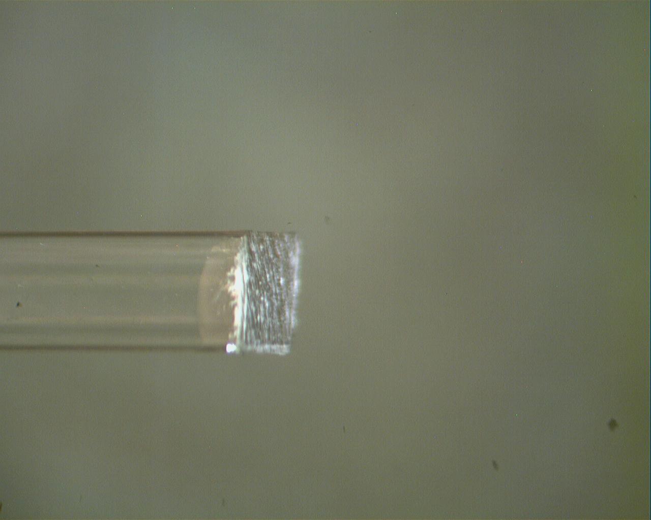
79 KB | This is a picture of a cleaved fiber after using the "Emery" buff. | 1 |
| 17:49, 10 October 2007 | Polishing Tool.JPG (file) |  |
568 KB | These are the polishing tools that I used. Note that the part of the buffs that are on the metal plate are the removed backs of the buffs and are mounted on the plate, not just resting. | 1 |
| 17:46, 10 October 2007 | Condition.jpg (file) |  |
83 KB | This is a picture of a cleaved fiber after using the "#2 Condition" buff. | 1 |
| 17:44, 10 October 2007 | Shine.jpg (file) |  |
82 KB | This is a picture of a cleaved fiber after using the "#3 Shine" buff. | 1 |
| 17:42, 10 October 2007 | Clean.jpg (file) |  |
71 KB | This is a picture of a cleaved fiber after using the "#1 Clean" buff. | 1 |
| 17:12, 14 September 2007 | Workstandassembled.jpg (file) |  |
31 KB | 1 |