Uploads by Krueger
Jump to navigation
Jump to search
This special page shows all uploaded files.
| Date | Name | Thumbnail | Size | Description | Versions |
|---|---|---|---|---|---|
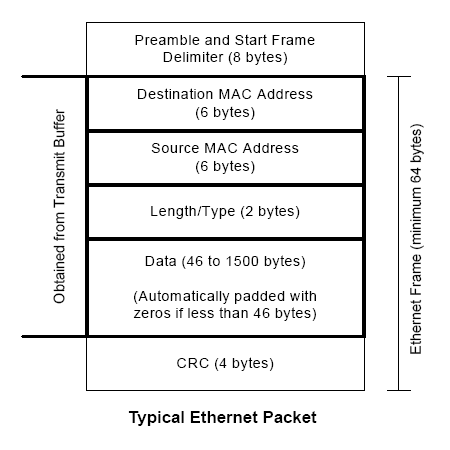
| 13:58, 17 July 2007 | Ethernet packet.PNG (file) |  |
20 KB | An Ethernet packet. Image excerpted from Silicon Laboratories CP2200/1 data sheet. | 1 |
| 20:04, 9 July 2007 | ISE - Simulation.PNG (file) |  |
82 KB | Xilinx ISE WebPACK 9.1.03i; simulation results view. | 1 |
| 19:53, 9 July 2007 | ISE - TBW.PNG (file) |  |
75 KB | Xilinx ISE WebPACK 9.1.03i; test bench waveform editor. | 1 |
| 19:40, 9 July 2007 | ISE - Make New TBW.PNG (file) |  |
94 KB | Xilinx ISE WebPACK 9.1.03i; new test bench waveform creation wizard. | 1 |
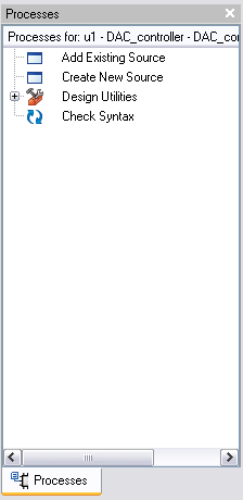
| 19:21, 9 July 2007 | Processes Synthesis-Implementation - non-top module.PNG (file) |  |
7 KB | Xilinx ISE WebPACK 9.1.03i; Processes box, Synthesis/Implementation view, file not set as top module. | 1 |
| 19:12, 9 July 2007 | ISE - Code.PNG (file) |  |
97 KB | Xilinx ISE WebPACK 9.1.03i; VHDL editor view. | 1 |
| 19:11, 9 July 2007 | ISE - RTL.PNG (file) |  |
71 KB | Xilinx ISE WebPACK 9.1.03i; Register Transfer Level Schematic | 1 |
| 19:05, 9 July 2007 | Processes Synthesis-Implementation.PNG (file) |  |
13 KB | Xilinx ISE WebPACK 9.1.03i; Processes box, Synthesis/Implementation view. | 1 |
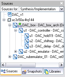
| 18:46, 9 July 2007 | Sources Synthesis-Implementation.PNG (file) |  |
10 KB | Xilinx ISE WebPACK 9.1.03i; Sources box, Synthesis/Implementation view. | 1 |
| 22:11, 5 July 2007 | Spartan.jpg (file) |  |
6 KB | Xilinx Spartan-3 logo | 1 |
| 18:37, 5 July 2007 | Temp Controller Block.JPG (file) |  |
108 KB | Functional block diagram for the temperature sensor controller. Inputs are on the top left and outputs are on the top right. | 1 |
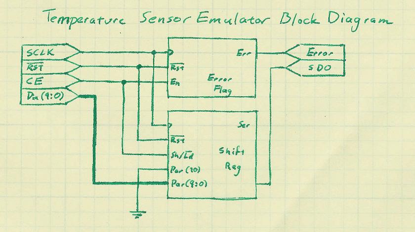
| 18:36, 5 July 2007 | Temp Emulator Block.JPG (file) |  |
51 KB | Functional block diagram for the temperature sensor emulator. Inputs are on the top left and outputs are on the top right. | 1 |
| 18:35, 5 July 2007 | DAC Emulator Block.JPG (file) |  |
113 KB | Functional block diagram for the DAC emulator. Inputs are on the top left and outputs are on the top right. | 1 |
| 18:33, 5 July 2007 | DAC Controller Block.JPG (file) |  |
87 KB | Functional block diagram for the DAC controller. | 1 |
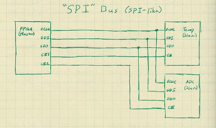
| 18:30, 5 July 2007 | SPI-like bus.JPG (file) |  |
67 KB | Initial plan for topology of the SPI-based bus used to connect the temperature sensor and the ADC to the FPGA. Note that in proper SPI bus nomenclature SDI and SDO would be swapped on the master (master's input is slave's output and vice-versa), but were | 1 |
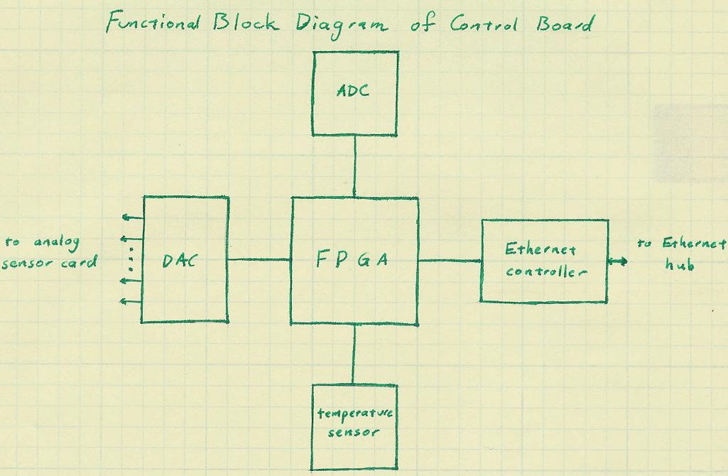
| 18:12, 5 July 2007 | Control Board Functional Block.JPG (file) |  |
68 KB | The functional block diagram for the digital control board, showing the interconnections of the components and the buses to off-board parts (the analog board to the left, the Ethernet switch to the right). | 1 |
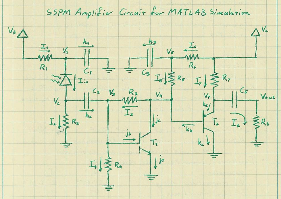
| 18:51, 3 July 2007 | SSPM Amplifier Circuit Diagram.jpg (file) |  |
102 KB | Circuit diagram for SiPM amplifier | 1 |
| 18:04, 3 July 2007 | Amplifier Response to Power (2007-07-03).png (file) | .png) |
11 KB | Photonique's SiPM amplifier response to varying power voltages. | 1 |
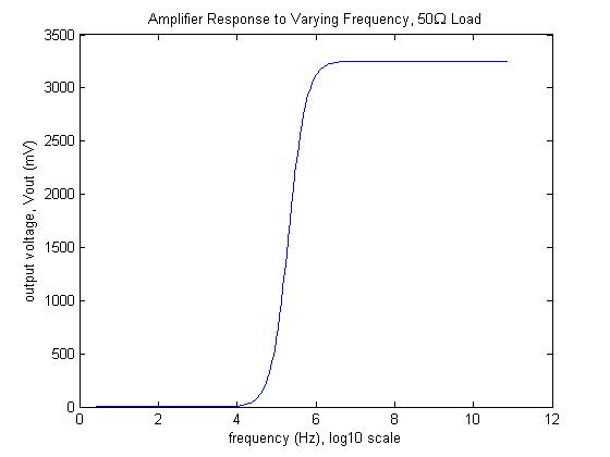
| 18:03, 3 July 2007 | Amplifier Response to Frequency (2007-07-03).png (file) | .png) |
9 KB | Photonique's SiPM amplifier response to varying frequency, semi-log (lin-log10) plot. | 1 |
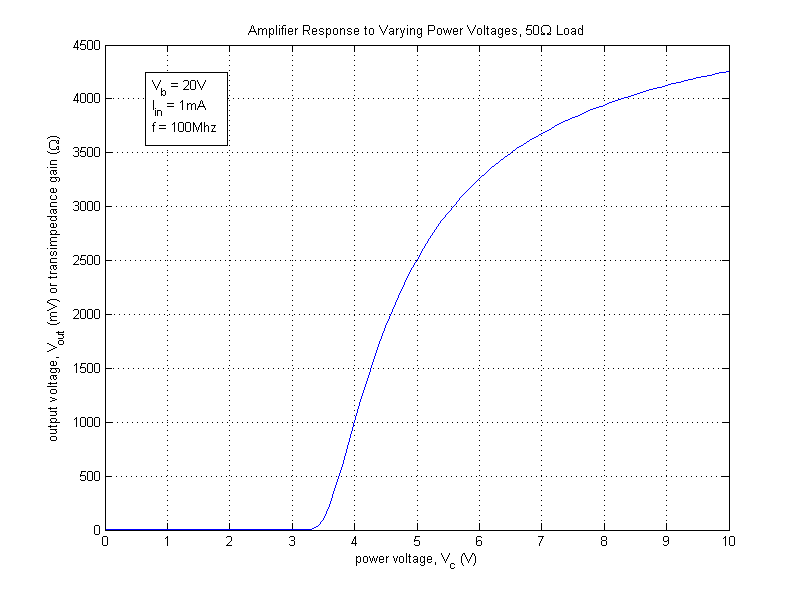
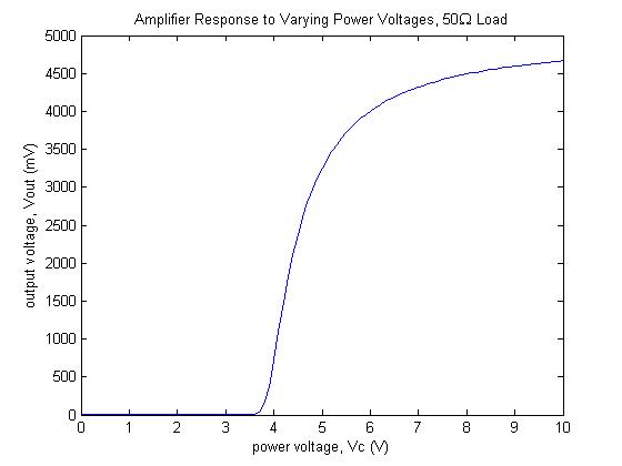
| 15:07, 2 July 2007 | Amplifier Response to Power.jpg (file) |  |
21 KB | Response of MATLAB SiPM model to varying power voltages. | 1 |
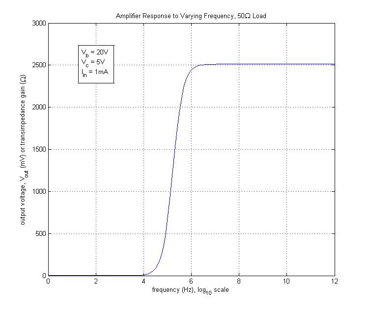
| 15:05, 2 July 2007 | Amplifier Response to Frequency.jpg (file) |  |
18 KB | Response of MATLAB SiPM model to varying frequencies. | 1 |