The rates in the recoil proton detector are about two orders of
magnitude smaller than in the tagger, whereas the time scale for
the electronics is the same. Therefore all dead time effects in
the circuits that produce the RPD OR are ignored. Logically the
RPD OR is more complicated than the tagger OR: it is composed in
the following way. First each of the 12 thick (E) counters is
AND'ed with its corresponding thin (G) counter, then these 12
coincidence signals are combined together in an OR. The width of
the coincidence gate is ignored (set to zero) in the model, and
the rate is a linear function of the beam current.
| (4) |
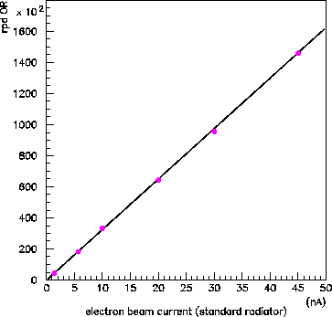
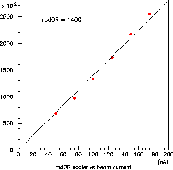
The value of ![]() varied significantly during the run, depending in
particular on the threshold and gains in the RPD counters, and to some
extent on the quality of the beam tune. The difference between scans
taken at the beginning of the June period and the end can be seen by
comparing Fig. 3 with Fig. 4. The decrease in slope
by a factor of 2.5 is mainly due to raising the RPD discriminator
threshold. The deviation from a straight line during the high-current
scan in Fig. 4 is due to changing beam conditions during that
scan; CLAS emptied and refilled their target during this scan. The
effect of the CLAS target is much more apparent in the UPV rate, shown
below. The principal restriction on this part of the model is that the
RPD rate must not exceed the level where electronics dead times begin
to be important, around 5-10MHz in the OR. Given that this corresponds
to
varied significantly during the run, depending in
particular on the threshold and gains in the RPD counters, and to some
extent on the quality of the beam tune. The difference between scans
taken at the beginning of the June period and the end can be seen by
comparing Fig. 3 with Fig. 4. The decrease in slope
by a factor of 2.5 is mainly due to raising the RPD discriminator
threshold. The deviation from a straight line during the high-current
scan in Fig. 4 is due to changing beam conditions during that
scan; CLAS emptied and refilled their target during this scan. The
effect of the CLAS target is much more apparent in the UPV rate, shown
below. The principal restriction on this part of the model is that the
RPD rate must not exceed the level where electronics dead times begin
to be important, around 5-10MHz in the OR. Given that this corresponds
to ![]() tagged photons/s, this part of the model is free of
restrictions.
tagged photons/s, this part of the model is free of
restrictions.