Difference between revisions of "Moving the Tagger Microscope"
| Line 31: | Line 31: | ||
| − | Moving the TAGM to a new energy range not only involves the physical relocation of the microscope and its shielding along the tagger magnet's focal plane, but also requires internal realignment of the fiber, which is the subject of this page. The realignment of the scintillating fibers' longitudinal axes requires all 17 bundle supports to have new, individual crossing angles (&beta angle) with respect to the focal plane. These angles are derived from a table generated based on a TOSCA map of the post-bremsstrahlung crossing angles as they pass through the magnet's focal plane. Since the crossing angle changes with energy (e.g. displacement along the focal plane) each bundle support will have a slight "kick" or "tow" from the adjacent bundle support. The tow is typically on the order of 0.1<sup>o</sup>. | + | Moving the TAGM to a new energy range not only involves the physical relocation of the microscope and its shielding along the tagger magnet's focal plane, but also requires internal realignment of the fiber, which is the subject of this page. The realignment of the scintillating fibers' longitudinal axes requires all 17 bundle supports to have new, individual crossing angles (β angle) with respect to the focal plane. These angles are derived from a table generated based on a TOSCA map of the post-bremsstrahlung crossing angles as they pass through the magnet's focal plane. Since the crossing angle changes with energy (e.g. displacement along the focal plane) each bundle support will have a slight "kick" or "tow" from the adjacent bundle support. The tow is typically on the order of 0.1<sup>o</sup>. |
| + | |||
| + | Since the bundle supports have varying β angles, the parallel railing system that holds these supports in place are no longer representative of their namesake. That is, the front and rear rails of the parallel railing system are not parallel to each other and have a pitch with respect to one another. For each individual energy range covered by the microscope, or more simply stated for each energy that the microscope starts at, a new pitch for the parallel rails must be determined and three components unique to that starting energy must be fabricated. For this reason CAD drawings, an Excel spreadsheet, and this wiki page were created to provide the information needed to realign and move the TAGM to the following starting photon energies: 11, 10, 9, 8, 7, 6.5, 6, 5.5, and 5 GeV. The turnaround time for the machining components is typically two to five days, while the realignment of fibers will take no more than two days with inexperienced workers, and that's being conservative. | ||
==Coordinate System== | ==Coordinate System== | ||
Revision as of 03:11, 25 March 2021
| Important Documents |
| 3D Printer Manual |
| PLA Filament MSDS |
| ABS Filament MSDS |
| UConn EHS 3D Printer Approval |
| [| Ben's Logbook] |
Moving the Tagger Microscope Along the Focal Plane
Tagger Microscope

- Prior to Installation in the Tagger Hall
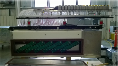
Figure 2: TAGM just prior to installation in the Tagger Hall. The side of the TAGM seen here will face towards the Tagger Magnet.
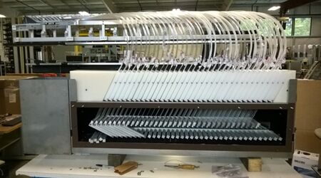
Figure 3: TAGM during reassembly just prior to installation in the Tagger Hall. The side of the TAGM seen here will face away from the Tagger Magnet when installed.


The tagger microscope (TAGM) consists of six major components: upper enclosure, lower enclosure, optical fibers, electronics, shielding, and darkening shroud. As seen from the CAD image above, Figure 1, the lower enclosure houses the microscope's electronics, while the upper enclosure contains the optical fiber bundle supports (a.k.a. popsicle sticks). The bundle supports are used to align the scintillating fiber (SciFi) longitudinal axis to the incoming electron's path angle as it passes through the tagger magnet's focal plane. The designed angular tolerance, e.g. fiber to electron allowable angular error, is < 0.5o. MC simulations were performed to test the effect of various amounts of misalignment between the electron angle and the SciFi axis. Figure 4 shows a plot of one of these simulations with the solid line showing the scintillation response of the central fiber, while the dashed lines are the response for the adjacent fibers. A factor of three separation between adjacent signal amplitudes is achievable when alignment is < 3o. In order to achieve optimal alignment, similar to < 0.2o that was seen in bench tests, the SciFi end of the optical fibers are affixed to bundle supports (Figure 5) in the upper enclosure, with the light guide potion of the fiber extending down to silicon photomultipliers (SiPMs) located on preamplifier boards (Figure 6) in the lower enclosure.
- The two ends of the optical fibers
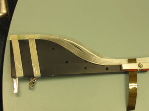
Figure 5: Picture taken during testing phase of a bundle support with mounted fibers. Note that the bundle support does not have its mounting rods installed. These rods are used to secure the bundle support to the parallel railing system located in the upper enclosure.
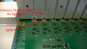
Figure 6: Image of the preamplifier board and open chimney (light guide holder) before fiber installation. The chimney aligns the 2mm2 lightguide end to the center of the 3mm2 active area of the SiPM with only a 0.5mm air gap between the two.


Moving the TAGM to a new energy range not only involves the physical relocation of the microscope and its shielding along the tagger magnet's focal plane, but also requires internal realignment of the fiber, which is the subject of this page. The realignment of the scintillating fibers' longitudinal axes requires all 17 bundle supports to have new, individual crossing angles (β angle) with respect to the focal plane. These angles are derived from a table generated based on a TOSCA map of the post-bremsstrahlung crossing angles as they pass through the magnet's focal plane. Since the crossing angle changes with energy (e.g. displacement along the focal plane) each bundle support will have a slight "kick" or "tow" from the adjacent bundle support. The tow is typically on the order of 0.1o.
Since the bundle supports have varying β angles, the parallel railing system that holds these supports in place are no longer representative of their namesake. That is, the front and rear rails of the parallel railing system are not parallel to each other and have a pitch with respect to one another. For each individual energy range covered by the microscope, or more simply stated for each energy that the microscope starts at, a new pitch for the parallel rails must be determined and three components unique to that starting energy must be fabricated. For this reason CAD drawings, an Excel spreadsheet, and this wiki page were created to provide the information needed to realign and move the TAGM to the following starting photon energies: 11, 10, 9, 8, 7, 6.5, 6, 5.5, and 5 GeV. The turnaround time for the machining components is typically two to five days, while the realignment of fibers will take no more than two days with inexperienced workers, and that's being conservative.
Coordinate System
There are three coordinate systems often referred to inside the GlueX Tagger Hall. These coordinate systems have origins associated with the Goniometer center (room coordinates), Tagger Magnet center (map coordinates), and the focal plane (FP coordinates). The room coordinate system has the positive z-coordinate along the beam axis with the positive y direction pointing to the ceiling of the tagger hall from the coordinates origin placed at the Goniometer's center, where the beamline radiator is located. Figure 1 shown below, taken from a presentation by Dan Sober, shows the three coordinate systems relative to one another. The map coordinate system (magnetic mapping) places the y-coordinate along the long axis of the magnet with the positive x-axis parallel to the tagger hall floor in the direction of the focal plane. the positive z-axis of the map coordinate system points toward the tagger hall ceiling. When viewed from above the map y-coordinate is offset from the room coordinate z-axis by 6.5 degrees towards the focal plane (clockwise). The focal plane coordinate system places its x-axis along the electron focal plane with zero being at an electron energy equivalent to a photon energy around 11.7 GeV. The positive x-axis points toward increasing electron energy (decreasing photon energy). The positive y-axis of the focal plane coordinate system points towards the tagger magnet and is parallel to the tagger hall floor. This leaves the focal plane positive z-axis pointing towards the tagger hall ceiling.

In Spring 2017 a survey of the various beamline components saw a small change in the Tagger Microscope position. The Microscope (upstream center) position derived from this survey is shown below and includes a magnet center shift from previous measurements.
|
|||||||
| X room = | - 1.16666 m | ||||||
| Z room = | 7.41009 m | ||||||
| Angle room = | - 8.05220o | ||||||
|
|||||
| X map = | 0.73488 m | ||||
| Y map = | 1.22645 m | ||||
| X FP = | 3.31245 m | ||||
| Y FP = | -0.00932 m | ||||
Bundle Support (aka Popsicle Stick)
The Tagger Microscope (TAGM) contains 17 optical fiber bundle, each consists of a 5x6 array of 30 fibers for a total of 510 fibers (5 rows, 102 columns). Figure 2 below shows the fiber array as viewed by the electrons passing through the tagger magnet focal plane. Each optical fiber consists of a 2 mm2 x 2 cm BCF-20 scintillating fiber (SciFi) thermally fused to 2 mm2 x 165 cm BCF-98 light guide, see Figures 3 & 4. The SciFi end of each fiber is thermally bent into an "S" shape to remove the fiber from the electrons' path soon after passing through the SciFi, see Figure 5. The fiber begins its bend out of the electrons' path after only 4.5 cm. This length provides enough material past the fused joint to minimize strain on the joint resulting from the bend and fiber mounting straps, while also reducing the material in the line-of-fire that could result in backscatter.

- Transmission of scintillation light
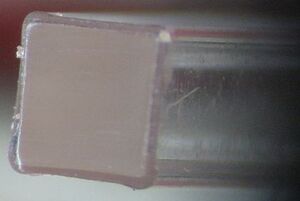
Figure 3: An end view of a 2 mm2 light guide fiber (BCF-98).
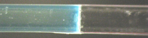
Figure 4: The mating of 2 cm. of scintillating fiber BCF-20 (left) joined to 165 cm. light guide fiber BCF-98 (right).


xxxxxx
xxxxxx
Final
xxxxxxxxxxxxx