Difference between revisions of "Pratt/optics rail"
Jump to navigation
Jump to search
(Created page with '*This page is for the use of Dr. Richard T. Jones to display the progress made with the laser ablation optics system. {| cellpadding="3" style="text-align:center; margin: 1em au…') |
|||
| Line 2: | Line 2: | ||
{| cellpadding="3" style="text-align:center; margin: 1em auto 1em auto" | {| cellpadding="3" style="text-align:center; margin: 1em auto 1em auto" | ||
|- | |- | ||
| − | | [[File:long_view_rail.jpg|right|thumb]] || || [[File:Brendan-optics.jpg|left|thumb]][[File:Stage_lens_sensor.jpg|right|thumb]] || || [[File:Longview_optics.jpg|left|thumb]] || || [[File:optics-laser.jpg|left|thumb]] || || [[File:optics_laser_scope.jpg|left|thumb]] || || [[File:Longview_oscilloscope.jpg|left|thumb]] | + | | [[File:long_view_rail.jpg|right|thumb]] || || [[File:Brendan-optics.jpg|left|thumb]]|| ||[[File:Stage_lens_sensor.jpg|right|thumb]] || || [[File:Longview_optics.jpg|left|thumb]] || || [[File:optics-laser.jpg|left|thumb]] || || [[File:optics_laser_scope.jpg|left|thumb]] || || [[File:Longview_oscilloscope.jpg|left|thumb]] |
|- | |- | ||
|} | |} | ||
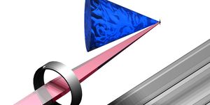
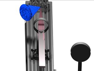
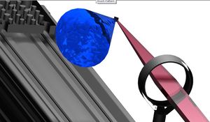
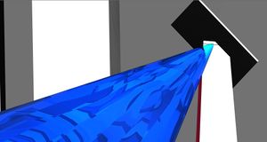
| − | *These photos are taken from a TurboCAD rendering of the optics rail that I completed this week. I have also added the 0.5cm x 0.5cm x 100 micron thick diamond at the optimum focal length ([http://zeus.phys.uconn.edu/wiki/index.php/Diamond_Radiator_Thinning_Using_an_Excimer_Laser 17cm]) and tilted at a 45 | + | *These photos are taken from a TurboCAD rendering of the optics rail that I completed this week. I have also added the 0.5cm x 0.5cm x 100 micron thick diamond at the optimum focal length ([http://zeus.phys.uconn.edu/wiki/index.php/Diamond_Radiator_Thinning_Using_an_Excimer_Laser 17cm]) and tilted at a 45 degree angle from the beam axis. The blue cone represents the ablation plume and its dimensions are taken from plume characteristics observed in local thin film ablation laboratories. |
| + | {| cellpadding="3" style="text-align:center; margin: 1em auto 1em auto" | ||
|- | |- | ||
| [[File:opticsB.jpg|right|thumb]] || || [[File:opticsC.jpg|left|thumb]][[File:opticsD.jpg|right|thumb]] || || [[File:opticsE.jpg|left|thumb]] || || [[File:optics.BlastTCW.jpg|left|thumb]] || || [[File:rail.jpg|left|thumb]] || || [[File:blastII.jpg|left|thumb]] || || [[File:diamond_blast.jpg|left|thumb]] | | [[File:opticsB.jpg|right|thumb]] || || [[File:opticsC.jpg|left|thumb]][[File:opticsD.jpg|right|thumb]] || || [[File:opticsE.jpg|left|thumb]] || || [[File:optics.BlastTCW.jpg|left|thumb]] || || [[File:rail.jpg|left|thumb]] || || [[File:blastII.jpg|left|thumb]] || || [[File:diamond_blast.jpg|left|thumb]] | ||
|- | |- | ||
|} | |} | ||
Revision as of 19:18, 7 May 2010
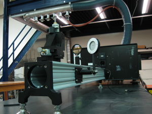
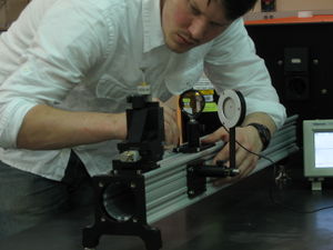
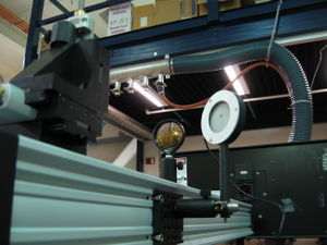
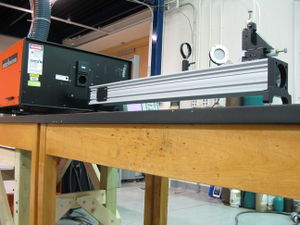
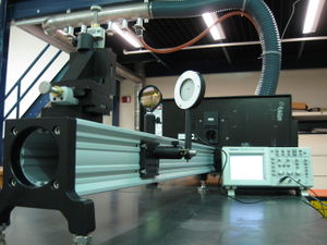
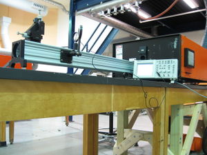
- This page is for the use of Dr. Richard T. Jones to display the progress made with the laser ablation optics system.
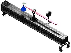
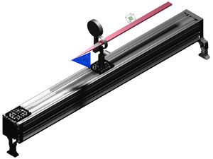
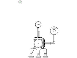
- These photos are taken from a TurboCAD rendering of the optics rail that I completed this week. I have also added the 0.5cm x 0.5cm x 100 micron thick diamond at the optimum focal length (17cm) and tilted at a 45 degree angle from the beam axis. The blue cone represents the ablation plume and its dimensions are taken from plume characteristics observed in local thin film ablation laboratories.
