Difference between revisions of "Calibration Device for Scintillators"
| Line 42: | Line 42: | ||
====Electronics==== | ====Electronics==== | ||
*To operate the linear motion stage, a series of electronics is set up that works together to move the pulley system. First a computer program built with Labview was created to communicate with the Digital to Analog Controller(DAC) via USB. The DAC has pin-outs arranged similarly to a serial port, that control the driver. The R208 microstep driver has various wires connected to the DAC. When the circuits are opened and closed via the Labview program, the stepper motor steps forward or backward. From the driver, the 5V logic power wire is connected to the 5V output on the DAC and the 24V, 2 Amp power driver wire is connected to the power supply. The logic ground and power ground are also connected to the power supply ground. The stepper motor in use is a 1.8 degree high-torque model with a four wire connection.[[File:Electronic Setup.JPG|thumb|Electronics]] | *To operate the linear motion stage, a series of electronics is set up that works together to move the pulley system. First a computer program built with Labview was created to communicate with the Digital to Analog Controller(DAC) via USB. The DAC has pin-outs arranged similarly to a serial port, that control the driver. The R208 microstep driver has various wires connected to the DAC. When the circuits are opened and closed via the Labview program, the stepper motor steps forward or backward. From the driver, the 5V logic power wire is connected to the 5V output on the DAC and the 24V, 2 Amp power driver wire is connected to the power supply. The logic ground and power ground are also connected to the power supply ground. The stepper motor in use is a 1.8 degree high-torque model with a four wire connection.[[File:Electronic Setup.JPG|thumb|Electronics]] | ||
| + | *The user can select a left or right direction, how many steps per interval, the number of iterations and the time delay between iterations. The program tracks the current location of the rail carriage based on the number of degrees rotated. | ||
| + | [[Front Panel Control.JPG|thumb|Front Panel]] | ||
| − | |||
====Structure==== | ====Structure==== | ||
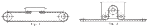
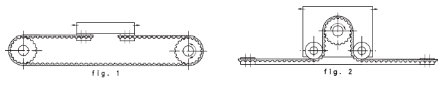
*The main feature of the linear motion stage is the heavy duty optical rail the carriage moves along. Two pulley mounts designed in Turbocad and fabricated out of aluminum are used to hold up the pulleys and attach the stepper motor. The mounts are fasted to the optical rail using bolts attached to rail clamps. A belt is placed connecting the two pulleys and is tightened using the rail clamps on the optical bar. The rail carriage that will house the calibration source is attached to the belt via a metal clamp. The linear motion stage will not only be effective moving precision distances to calibrate the fiber array, but it is rigid enough to be used as a structural beam in the construction of the tagger microscope. | *The main feature of the linear motion stage is the heavy duty optical rail the carriage moves along. Two pulley mounts designed in Turbocad and fabricated out of aluminum are used to hold up the pulleys and attach the stepper motor. The mounts are fasted to the optical rail using bolts attached to rail clamps. A belt is placed connecting the two pulleys and is tightened using the rail clamps on the optical bar. The rail carriage that will house the calibration source is attached to the belt via a metal clamp. The linear motion stage will not only be effective moving precision distances to calibrate the fiber array, but it is rigid enough to be used as a structural beam in the construction of the tagger microscope. | ||
Revision as of 18:28, 5 May 2011
Atoms contain nuclei that are made up of protons and neutrons which are comprised of quarks. These quarks are confined inside protons and neutrons by powerful bonds that are generated by the strong nuclear force of attraction between them. Particle physicists visualize these bonds as “channels” that form between the quarks, over which they continuously exchange virtual particles known as gluons. A new particle physics experiment, GlueX, is being constructed at the Thomas Jefferson National Accelerator Facility (Jefferson Lab) in Newport News Virginia, with the capability to excite the gluonic bonds between quarks and study their dynamics.
To do this, the GlueX experiment requires a beam of polarized light (photons) with a very short wavelength, in the gamma ray spectrum. This beam of polarized photons is created by passing high-energy electrons from the Jefferson Lab accelerator through an oriented diamond crystal, such that they emit coherent bremsstrahlung radiation. The energy of each photon in the beam is “tagged” by detecting the electron that produced it in a scintillating fiber array called the tagging microscope.
To calibrate the tagging microscope, a source mounted on a linear motion stage has been designed and fabricated. The design, assembly and initial tests of this system is described.
Ideas
- Printer disassembly and take-over of printer head linear motion through use of parallel port programming with C
- Worm gear connected to DC motor with micro controller set up
- Linear Rail system
Stepper Motor Belt System was chosen
Printer's Linear Motion
- Disassembled printer casing
- Installed cygwin on computer for C interface and read up on programming language C
- Investigated Computer Numerical Control but found it was not useful for this application
- Investigated serial port programming and the use of Printer Control Language on an HP printer documentation on PCL
Parallel Port Programming
- Interfacing directly to the printer proved very challenging [1]
- Unsuccessfully accessed printer
Worm Gear
- Spinning a long grooved metal cylinder gear requires a lot of torque
- Minimal support for head motion
- DC motor with time steps is not as effective as stepper motor
Rail System
- Has internal motion control
- Very costly
- Too heavy duty for this application
Belt System
- Stepper motor with micro controller stands stationary on one end and calibration device would be connected to a slide rail system for stability
 Clamping Plate Setup http://www.polytechdesign.com/images/gears_01.gif
 - We need to find something that is low cost but is accurate enough to be stopped at each fiber array block. Because the intended calibration source is most likely going to have a wide range, the step size does not have to be too small.
- For support: Overhead Enclosed-Track Conveyor Bracket, linear guide rail


Beam Deflection
- The deflection at the center of the slide rail is calculated using a simply end supported beam as a model with beam deflection equations considering the weight of the bar and the weight of the cart. The maximum deflection was calculated as not exceeding 6um, well within the limit for our usage.
Motor
- LinEngineering 1.8 Degree Motor 'WO-5718X-05E' was found to be appropriate and cost effective. [2]
- With a LinEngineering 1.8 Degree Motor and a radius of .5" for the pulley, the step size would be 0.005" or 0.127mm which is well within a 2mm scintillator.
Electronics
- To operate the linear motion stage, a series of electronics is set up that works together to move the pulley system. First a computer program built with Labview was created to communicate with the Digital to Analog Controller(DAC) via USB. The DAC has pin-outs arranged similarly to a serial port, that control the driver. The R208 microstep driver has various wires connected to the DAC. When the circuits are opened and closed via the Labview program, the stepper motor steps forward or backward. From the driver, the 5V logic power wire is connected to the 5V output on the DAC and the 24V, 2 Amp power driver wire is connected to the power supply. The logic ground and power ground are also connected to the power supply ground. The stepper motor in use is a 1.8 degree high-torque model with a four wire connection.
- The user can select a left or right direction, how many steps per interval, the number of iterations and the time delay between iterations. The program tracks the current location of the rail carriage based on the number of degrees rotated.

Structure
- The main feature of the linear motion stage is the heavy duty optical rail the carriage moves along. Two pulley mounts designed in Turbocad and fabricated out of aluminum are used to hold up the pulleys and attach the stepper motor. The mounts are fasted to the optical rail using bolts attached to rail clamps. A belt is placed connecting the two pulleys and is tightened using the rail clamps on the optical bar. The rail carriage that will house the calibration source is attached to the belt via a metal clamp. The linear motion stage will not only be effective moving precision distances to calibrate the fiber array, but it is rigid enough to be used as a structural beam in the construction of the tagger microscope.
To Do
- Integrate rotary encoder in labview program
- Further investigation needs to be done concerning the type of source and mounting setup needed for the calibrator. The final dimensions of the tagger microscope is not yet known, so further work has to be done to establish a final location for this optical rail and calibration arm. Specifically with regards to the source, the frequency and power of the source must be determined, as well as the focusing mechanism.