Difference between revisions of "Microscope Prototype Mechanical Design Drawings"
Jump to navigation
Jump to search
| Line 52: | Line 52: | ||
*Pin-out of Euro Connector Right Angle Receptacle-96pin ([http://www.phys.uconn.edu/~mcintyre/workfiles/End%20of%20Semester%20Project/Euro%20Connectors/PinOut-EuroPlug-96pin-RightAngle.pdf PDF]) | *Pin-out of Euro Connector Right Angle Receptacle-96pin ([http://www.phys.uconn.edu/~mcintyre/workfiles/End%20of%20Semester%20Project/Euro%20Connectors/PinOut-EuroPlug-96pin-RightAngle.pdf PDF]) | ||
| − | *Mechanical Data Sheets (Folder) | + | *Mechanical Data Sheets ([http://www.phys.uconn.edu/~mcintyre/workfiles/End%20of%20Semester%20Project/Mechanical%20Data%20Sheets/ Folder]) |
*Scintillating Optical Fibers Brochure ([http://www.phys.uconn.edu/~mcintyre/workfiles/End%20of%20Semester%20Project/SGC_Scintillating_Optical_Fibers_Brochure.pdf PDF]) | *Scintillating Optical Fibers Brochure ([http://www.phys.uconn.edu/~mcintyre/workfiles/End%20of%20Semester%20Project/SGC_Scintillating_Optical_Fibers_Brochure.pdf PDF]) | ||
| Line 63: | Line 63: | ||
*Pictures of the Prototype Set-up Prior to Welding ([http://www.phys.uconn.edu/~mcintyre/workfiles/End%20of%20Semester%20Project/Set-up-Pics/ Folder]) | *Pictures of the Prototype Set-up Prior to Welding ([http://www.phys.uconn.edu/~mcintyre/workfiles/End%20of%20Semester%20Project/Set-up-Pics/ Folder]) | ||
| − | |||
| − | |||
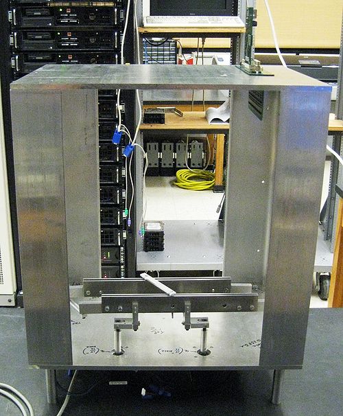
*Pictures Non-Welded Frame ([http://www.phys.uconn.edu/~mcintyre/workfiles/End%20of%20Semester%20Project/Non-Welded%20Frame/ Folder]) | *Pictures Non-Welded Frame ([http://www.phys.uconn.edu/~mcintyre/workfiles/End%20of%20Semester%20Project/Non-Welded%20Frame/ Folder]) | ||
| − | *Glued Spacer | + | *Pictures of the Glued Spacer on the Amp Board ([http://www.phys.uconn.edu/~mcintyre/workfiles/End%20of%20Semester%20Project/Glued%20Spacer%20Pics/ Folder]) |
| − | *Hall-B Beamline | + | *Pictures of the Hall-B Beamline ([http://www.phys.uconn.edu/~mcintyre/workfiles/End%20of%20Semester%20Project/Hall-B%20Beam-Line%20Pics Folder]) |
*Lowes Trip for Heat Treating Unit ([http://www.phys.uconn.edu/~mcintyre/workfiles/End%20of%20Semester%20Project/Lowes%20Trip/ Folder]) | *Lowes Trip for Heat Treating Unit ([http://www.phys.uconn.edu/~mcintyre/workfiles/End%20of%20Semester%20Project/Lowes%20Trip/ Folder]) | ||
Revision as of 11:06, 7 May 2010
TAGGER MICROSCOPE PROTOTYPE

 |
 |
 |
 |
 |
Purpose
The purpose of this page is to list the pertinent files used during the design and construction of the Prototype for the Tagger Microscope.
Repository
Mechanical Drawings
- Top Plate - Top View of Back-Plane, Amp. Board, & Card Guides (TurboCad v12 / AutoCad 2010)
- Top Plate – Holes & Cut-out (TurboCad v12 / AutoCad 2010)
- Top Plate – Holes to be drilled (TurboCad v12 / AutoCad 2010)
- Top Plate – Cut-Out only (Lab)5-3-2010.tcw TurboCad v12 / Lab)5-3-2010.dwg AutoCad 2010)
- Bottom Guard for Amplifier Board (TurboCad v12 / AutoCad 2010)
- Backplane Board (TurboCad v12 / AutoCad 2010)
- Amplifier Board (Board_May-6-2010.tcw TurboCad v12 / Board_May-6-2010.DWG AutoCad 2010)
- Digital Board (Board_May-6-2010.tcw TurboCad v12 / Board_May-6-2010.DWG AutoCad 2010)
- Bottom Plate (TurboCad v12 / AutoCad 2010)
- 4x4 mm Pack (TurboCad v12 / AutoCad 2010)
- Prototype Feet (TurboCad v12 / AutoCad 2010)
Data Sheets
- Sponge Gasket Data Sheet (PDF)
- Hardware Parts List (Excel)
- Pin-out of Euro Connector Receptacle-48pin (PDF)
- Pin-out of Euro Connector Receptacle-96pin (PDF)
- Pin-out of Euro Connector Right Angle Receptacle-96pin (PDF)
- Mechanical Data Sheets (Folder)
- Scintillating Optical Fibers Brochure (PDF)
- Scintillation Materials and Assemblies Brochure (PDF)
Pictures
- Pictures of the Amplifier Board Close-up (Folder)
- Pictures of the Prototype Set-up Prior to Welding (Folder)
- Pictures Non-Welded Frame (Folder)
- Pictures of the Glued Spacer on the Amp Board (Folder)
- Pictures of the Hall-B Beamline (Folder)
- Lowes Trip for Heat Treating Unit (Folder)