Tagger Microscope Placement in the Tagger Hall
UNDER CONSTRUCTION
Tagger Microscope Placement in the Tagger Hall
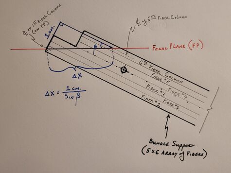
When discussing the location of the TAGM within the Tagger Hall it is often easiest to reference the starting point of the energy spectrum being tagged. So for example, if the TAGM is said to be placed at 9.2 GeV this would indicate that the location of the most upstream column of fibers, with respect to the beamline, is such that a post-bremsstrahlung electron associated with a 9.2 GeV emitted photon will pass through the longitudinal axis of this column of SciFi's. This column is referenced as column #1 in figure 1 below. As the column numbers increase the electrons' energy increases, and as such the energy of the associated photon being tagged decreases. The β angle of each bundle support, which as you recall holds an array of 5x6 fibers with a 2mm2 cross section, is selected to correspond to the average crossing angle for the electrons passing through these six columns. Therefore, for each bundle support there is a projection along this β angle that the support can be located. Since the crossing angle of the electrons only varies slightly over the bundle support width, there is a fair amount of play with the placement of the SciFi columns near the focal plane of the Tagger Magnet. To put this in prospective consider a bundle placed at 9.2 GeV. This 5x6 array of fibers will cover an energy range of 54 MeV and will see a change in β angle of only 0.11o.
A summary of the spreadsheet calculations is a follows:
- Select a starting energy for the photon tagging array (highest γ energy to tag)
- Using hodoscope energy bin bounds interpolate the crossing angle with respect to the focal plane (β1) of an electron associated the highest energy to be tagged (Eγo)
- Interpolate the location on the XFP axis at which this electron crosses (X1)
- These electrons will pass through the center of the first column of SciFi fibers
- Using β1 calculate the X-displacement along the focal plane (Δx) from the center of the first fiber column to the center of the sixth fiber column of the first bundle support
- Add Δx and X1 to get X6, then interpolate the value of β6
- Using the average value of β1 and β6 (βavg.), recalculate the XFP displacement (Δx) from the center of the first to sixth fiber column (X6)
- Repeat the above two steps until the bundle support angle β (e.g. average between β1 & β6) does not change appreciably
Now we know the focal plane crossing locations for the center of the first and sixth SciFi columns in our first bundle, as depicted in Figure 1 by the endpoints of Δx. Additionally, we know the β angle of the first bundle (noted as βavg above), which gives us the optimal alignment for each fiber in the bundle to their respective electron's path. The β angles for the first and sixth columns will be off by the same magnitude, but with opposite signs.
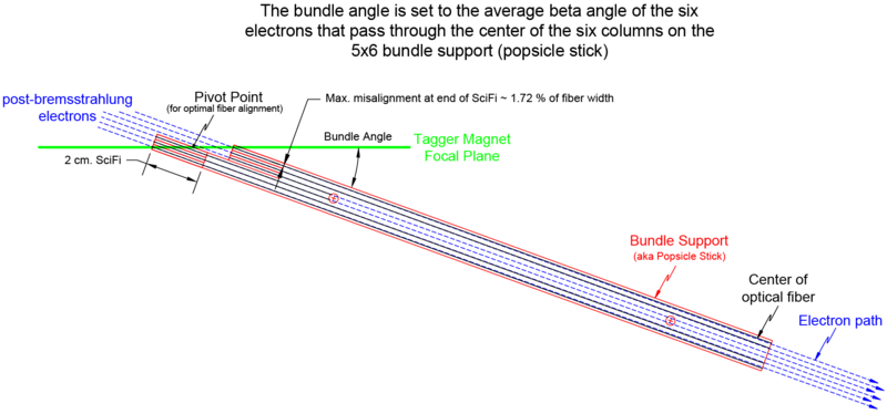
The 5x6 fiber bundle supports were designed with two 5x3 bundle halves offset such that the center of the front face of the middle column in each bundle half would sit on the magnetic focal plane for a β angle of 12.0o. This angle was selected as a compromise that would allow coverage through the photon energy range of 10 - 5.6 GeV.
As a side note - If required and finances permit, the 17 bundle supports can be easily redesigned for a different β angle. This redesign would take less than an hour of CAD work, with a manufacturing turn-around time in as little as two days. Costs are estimated to be around $2k. A CAD drawing of a new bundle support design already exists, which incorporates updated locations of the threaded holes for mounting the clamps that keep the bundle straps in place. The best time to replace/modify the bundle supports, if so desired, would be during fiber replacement. This way the new fibers can be mounted to the new bundle support outside the tagger hall, before ever making it to JLab. A conservative time estimate for changing the TAGM fiber configuration would be approximately two days (16 hours).
Each bundle has a "pivot point" that when placed on the focal plane, provides the optimal y-displacement from the focal plane for each fiber column in that bundle without encroaching too close to the tagger magnet window. If the bundle β angle ≠ 12o, then the 1st & 6th, 2nd & 5th, and 3rd & 4th fiber column pairs will have the same magnitude offset as one another from the focal plane in Y, but with opposite signs, see Figure 2. This is all provided that when the bundle support is mounted on the parallel railing system the tagger magnet's focal plane passes through the midpoint between the front and rear bundle halves (the so called pivot point).

