SiPM digital control board power supplies
Jump to navigation
Jump to search
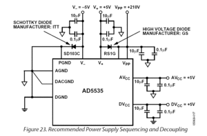
As seen in the SiPM digital control board netlist, the ICs on the control board have many different power requirements. In total there are 6 different voltages required. To minimize the number of actual power supplies needed, however, we plan on supplying only +5V, -5V, and +210V to the board from external power supplies. The other voltages will be created by appropriate voltage regulator ICs on the control board.
+5V supply
The +5V supply is responsible for powering most of the components on the control board. Here is a breakdown of those components by their voltage requirements. Voltages less than +5V will be created using voltage regulators
ICs requiring +5V
| IC Name | Pin Name | Tolerance | Current Requirements | Description | Notes |
| AD5535 | V+ | ±0.25V | 0.5mA typ, 1mA max | Positive amplifier | |
| AD5535 | AVCC | ±0.25V | 15mA typ, 18mA max | Analog supply | |
| AD7928 | AVDD | ±0.25V | 2.7mA max operating | AVDD can be as low as 2.7V if voltages measured never exceed 2.5V |
ICs requiring +3.3V
| IC Name | Pin Name | Tolerance | Current Requirements | Description | Notes |
| AD5535 | ANODE | large | set by external resistor | Temperature sensing diode | Diode drop varies w/ temperature. Requires external current limiting resistor. |
| AD5535 | REF_IN | ~±0.4V | 1.25uA max | Reference voltage | Should be as high as possible but not exceed AVCC-1.15V |
| AD7314 | VDD | ±0.3V | 1.2mA typ operating | Indicates ±1°C precision | |
| AD7928 | VDRIVE | ??? CMOS logic tolerance | 200uA | Logic output driver | |
| CP2201 | AV+ | ±0.3V | ??? | Analog supply pin | |
| CP2201 | VDD1 | ±0.3V | 75mA typ, 155mA max operating | Digital supply pin | |
| CP2201 | VDD2 | ±0.3V | 75mA typ, 155mA max operating | Digital supply pin |
+3.3V supply
Use for:
- AD5535 DAC
- ANODE
- Used for temperature monitoring. Voltage drop across a temperature sensitive diode allows AD7928 to measure internal temperature of AD5535. External resistor on AD5535 CATHODE will help to limit current draw.
- REF_IN supply
- Using +3.3V for REF_IN limits the SiPM amplifier bias voltages to a maximum of 165V. If greater variability is needed (up to +200V max), a separate +4V supply can be used for REF_IN, perhaps taken from the +5V rail via a voltage divider.
- ANODE
- AD7314 temperature sensor
- VDD supply
- indicates ±1°C accuracy
- should make compatible with 3.3V CMOS logic
- VDD supply
- AD7928 ADC
- VDRIVE output driver supply
- CP2201 Ethernet
- AV+ analog supply
- VDD1 digital supply
- VDD2 digital supply
- FPGA
- VCCAUX auxiliary supply
- Can also operate at +2.5V
- VCCO I/O logic supply
- Makes it compatible with 3.3V CMOS logic
- Puts it within acceptable range of voltages for communication with other ICs
- VCCAUX auxiliary supply
- XCF01S EEPROM
- VCCINT internal supply
- VCCO output driver
- Matches 3.3V I/O on FPGA
- VCCJ JTAG output driver
- Are we using this?
- AD5535 DAC
- V+ amplifier supply pins
- AVCC analog supply pins
- DVCC digital supply pins
- AD7928 ADC
- AVDD pins
- indicates measuring range of 0 to 2xREF_IN voltage
- AVDD pins
+1.2V supply
Use for:
- FPGA
- VCCINT internal logic supply
+2.5V supply
Use for:
- AD7928 ADC
- REF_IN reference supply
- Must be accurate to ±1%
- REF_IN reference supply
+5V supply
Use for:
- AD5535 DAC
- V+ amplifier supply pins
- AVCC analog supply pins
- DVCC digital supply pins
- AD7928 ADC
- AVDD pins
- indicates measuring range of 0 to 2xREF_IN voltage
- AVDD pins
-5V supply
Use for:
- AD5535 DAC
- V- amplifier supply pins
+210V supply
Use for:
- AD5535 DAC
- VPP high voltage supply
- Using this high voltage will allow for large adjustments of the SiPM amplifier bias voltages. Large variations may be necessary because the MATLAB model showed that adjustments between 0 and +50V had no effect on the SiPM.
- VPP high voltage supply
