Difference between revisions of "Microscope Electronics"
| (31 intermediate revisions by 2 users not shown) | |||
| Line 13: | Line 13: | ||
*[https://docs.google.com/document/d/1_-9WhsnsE3EcJ2LBc3zHJY16mdGlH9pc36KQKWYWNjk/edit '''Microscope Electronics Logbook'''] - [[User: Barnes|Alex Barnes]] | *[https://docs.google.com/document/d/1_-9WhsnsE3EcJ2LBc3zHJY16mdGlH9pc36KQKWYWNjk/edit '''Microscope Electronics Logbook'''] - [[User: Barnes|Alex Barnes]] | ||
*[https://drive.google.com/folderview?id=0B2pRO1LYzOwHOFFkaDdJeWNSTWM&usp=sharing '''Final Production Amplifier Logbooks'''] | *[https://drive.google.com/folderview?id=0B2pRO1LYzOwHOFFkaDdJeWNSTWM&usp=sharing '''Final Production Amplifier Logbooks'''] | ||
| − | *[ | + | *[[Media:FinalProductionPreamp.pdf|Final production pdf containing the schematics and layer-by-layer Altium drawings]] |
| + | *[[Media:Final_Production_Preamp_BOM.pdf|Bill of Materials]] | ||
| + | *[https://docs.google.com/spreadsheet/ccc?key=0AmpRO1LYzOwHdFpVWFU1RDZhWHoxTFlhNl9kOU00Tmc&usp=sharing SiPM Biases] | ||
==== Preamplifier Version 2.0 ==== | ==== Preamplifier Version 2.0 ==== | ||
*[https://docs.google.com/document/d/1y5JGcQqBFITXsLwghwjf4a7vX43x32BvP6NMIREKCCU/edit '''Preamp Version 2.0 Revision Notes'''] | *[https://docs.google.com/document/d/1y5JGcQqBFITXsLwghwjf4a7vX43x32BvP6NMIREKCCU/edit '''Preamp Version 2.0 Revision Notes'''] | ||
| − | *[ | + | *[[Media:PreampV2.0-SmartPDF.pdf|SmartPDF of Preamp Version 2.0]] |
| − | *[ | + | *[[Media:PreampV2.jpg|Picture of Preamp V2.0]] |
*[[List of Board Changes]] | *[[List of Board Changes]] | ||
| Line 28: | Line 30: | ||
*[[SiPM digital control board]] | *[[SiPM digital control board]] | ||
*[[Programming the FPGA|Flashing new firmware for FPGA]] | *[[Programming the FPGA|Flashing new firmware for FPGA]] | ||
| + | *[https://halldweb.jlab.org/DocDB/0023/002386/001/FPGA_finalfit-1-20-2014.tgz 1/2014 release of firmware for Vbias control board] | ||
| + | *[https://docs.google.com/document/d/1bxv-7gNciLGODSrxeMywemjbKlv3wrxJTU4ivEoAzwQ/edit?usp=sharing DAC Offset Measurement Guide] | ||
| + | *[https://docs.google.com/spreadsheet/ccc?key=0AmpRO1LYzOwHdDBfWkxOa0ZsenNUQl9KN2hUWVdOMnc&usp=sharing DAC Offset spreadsheet] | ||
| + | *[[Media:Api_specs.pdf|Control Board API from Hovanes]] | ||
| − | ==== Final Production ==== | + | ==== Final Production v1 ==== |
*[https://drive.google.com/folderview?id=0B2pRO1LYzOwHNFRkVGE1bEwzd1k&usp=sharing '''Final Production Control Board Logbooks'''] | *[https://drive.google.com/folderview?id=0B2pRO1LYzOwHNFRkVGE1bEwzd1k&usp=sharing '''Final Production Control Board Logbooks'''] | ||
| − | *[ | + | *[[Media:FinalProductionBiasControlBoard.pdf|Final production pdf containing the schematics and layer-by-layer Altium drawings]] |
| + | *[[Media:Final_Production_Bias_Control_BOM.pdf|Bill of Materials]] | ||
| + | * Multi-pin probe for FPGA chip - [[media:TQFPprobe-datasheet1of2.pdf|data sheet 1]], [[media:TQFPprobe-datasheet2of2.pdf|data sheet 2]] | ||
| + | |||
| + | ==== Final Production v2 ==== | ||
| + | Due to some DAC channels in the v1 set of boards not working properly and thus eliminating our set of spares, the control board has been remade. There were also changes to the physical v1 boards after fabrication that have been included in the schematics and pcb drawings in v2. | ||
| + | *[https://docs.google.com/document/d/13ZvpO1jstg648gXPRNS29l2FbfNmrvvEpKw07GCLuE8/edit?usp=sharing List of board changes from v1 to v2] | ||
| + | *[[Media:Bias_Control_BOM-3-9-2015.pdf|Bill of Materials]] | ||
| + | *[[Media:Bias_Control_Board_3-9-2015.pdf|Final production v2 pdf containing schematics and layer-by-layer Altium drawings]] | ||
=== Backplane === | === Backplane === | ||
| Line 42: | Line 56: | ||
*[https://drive.google.com/folderview?id=0B2pRO1LYzOwHbmdzTWdtNVhhNVU&usp=sharing '''Final Production Backplane Logbooks'''] | *[https://drive.google.com/folderview?id=0B2pRO1LYzOwHbmdzTWdtNVhhNVU&usp=sharing '''Final Production Backplane Logbooks'''] | ||
| − | *[ | + | *[[Media:FinalProductionBackplane.pdf|Final production pdf containing the schematics and layer-by-layer Altium drawings]] |
| − | + | *[[Media:Final_Production_Backplane_BOM.pdf|Bill of Materials]] | |
| + | *[[Media:Amphenol_Connectors|Amphenol connectors for the power cables]] | ||
=== Power Supply Requirements === | === Power Supply Requirements === | ||
| Line 67: | Line 82: | ||
#*fixed 4.95V - 5.05V, no adjustment required | #*fixed 4.95V - 5.05V, no adjustment required | ||
#*maximum current 3A (15W power) | #*maximum current 3A (15W power) | ||
| + | # -5V for DAC | ||
| + | #*fixed -4.95V - (-5.05V), no adjustment required | ||
| + | #*maximum current 65mA (0.325W power) | ||
The ripple specs for the 100V and the 6V power supplies are based on the two coupling curves shown below, for coupling from Vbias (top plot) and preamp VCC (bottom plot) into the output signal. The Vbias curve was computed assuming R18=100Ohms. | The ripple specs for the 100V and the 6V power supplies are based on the two coupling curves shown below, for coupling from Vbias (top plot) and preamp VCC (bottom plot) into the output signal. The Vbias curve was computed assuming R18=100Ohms. | ||
| Line 72: | Line 90: | ||
[[file:FinalPreampVbiasGainCurve.png|800px]] | [[file:FinalPreampVbiasGainCurve.png|800px]] | ||
[[file:FinalPreampVpowerGainCurve.png|800px]] | [[file:FinalPreampVpowerGainCurve.png|800px]] | ||
| + | |||
| + | ===Power Supply Design from Fernando B.=== | ||
| + | |||
| + | I recommend the following implementation for the TAGM supply system: | ||
| + | |||
| + | # One (1) MPOD-MINI - Wiener MPOD chassis, 5U high, 4 slots | ||
| + | # One (1) MPV8008LI - LV for preamps, logic (+5V, +6V) | ||
| + | # One (1) MPV8120I - Bias supplies for SiPMs (+100V). | ||
| + | |||
| + | Each of these supplies has 8 channels and we will use 6 from each. We will design a distribution box with inputs from the above supplies and 6 outputs; 6 cable assemblies will provide the proper supply levels to the 6 backplanes of the TAGM. | ||
| + | |||
| + | The above supplies meet or exceed your spec requirements on the wiki. Please review [http://www.wiener-d.com/sc/power-supplies/mpod--lvhv/mpod-mini-crate.html the supply specs here] and [http://www.wiener-d.com/sc/power-supplies/mpod--lvhv/mpod-lv-module.html here] | ||
| + | |||
| + | These implementation will cost less than $15k (chassis, modules, distribution boxes, cables, etc) and it is fully compatible, including controls, with the remaining systems in Hall D. Also note that there is a 12 week lead time so decision is urgent. | ||
| + | |||
| + | * [[media:LV&Bias_Distribution.pdf|LV and bias distribution drawings]] | ||
| + | * [[media:LV&Bias_Chassis.pdf|LV and bias supply cable wiring drawings]] | ||
== Hamamatsu MPPC SiPMs == | == Hamamatsu MPPC SiPMs == | ||
| Line 79: | Line 114: | ||
*[[media:Package.pdf|Package and Pad layout]] | *[[media:Package.pdf|Package and Pad layout]] | ||
*[[media:Hamamatsu SiPM MMPC spec sheet.pdf|Hamamatsu MMPC spec sheet]] | *[[media:Hamamatsu SiPM MMPC spec sheet.pdf|Hamamatsu MMPC spec sheet]] | ||
| − | + | [[file:SiPM-capacitance-curve.png|600px]] | |
== Pulse Generator == | == Pulse Generator == | ||
| − | *[[media: | + | *[[media:Pulser_circuit_diagram.pdf|Schematic of pulse generator]] |
*[[media:Parts for pulse generator.pdf|Parts for pulse generator]] | *[[media:Parts for pulse generator.pdf|Parts for pulse generator]] | ||
| − | *[ | + | *[[media:IMG_20120309_173350.jpg|Picture of Pulse Generator]] |
*[https://docs.google.com/a/uconn.edu/document/d/1CPsms64eeuY8-0f-OfW85xeqLvxdH1gx9Rk-Wd4UuB0/edit Jon Kulakofsky's pulse generator fixing notes] | *[https://docs.google.com/a/uconn.edu/document/d/1CPsms64eeuY8-0f-OfW85xeqLvxdH1gx9Rk-Wd4UuB0/edit Jon Kulakofsky's pulse generator fixing notes] | ||
| − | + | *[[Pulser amplitude feedback amplifier]] | |
== Presentations == | == Presentations == | ||
| − | *[ | + | *[[Media:Gluex_Collaboration_Meeting_May_2012.pptx|Gluex Collaboration Meeting May 2012]] |
*[http://argus.phys.uregina.ca/cgi-bin/private/DocDB/ShowDocument?docid=2155 '''Gluex Collaboration Meeting Feb. 2013'''] | *[http://argus.phys.uregina.ca/cgi-bin/private/DocDB/ShowDocument?docid=2155 '''Gluex Collaboration Meeting Feb. 2013'''] | ||
| − | + | *[http://argus.phys.uregina.ca/cgi-bin/private/DocDB/ShowDocument?docid=2079 '''Gluex Collaboration Meeting May 2013'''] | |
| + | *[http://argus.phys.uregina.ca/cgi-bin/private/DocDB/ShowDocument?docid=2340 '''Gluex Collaboration Meeting Oct. 2013'''] | ||
| + | * [[media:AlexBarnes-DNP2013.pdf|The Development and Construction of the Tagger Microscope for the GlueX Experiment]] (talk DNP-2013 Newport News, VA, 10/2013) - ''[[User: Barnes| Alex Barnes]]'' | ||
== Past Work == | == Past Work == | ||
| − | *[ | + | *[[Design and prototyping of SiPM electronics]] - [[User: Senderovich|Igor Senderovich]] |
Latest revision as of 22:43, 30 January 2018
Electronics
The GlueX experiment will use a 9 GeV linearly polarized photon beam to search for mesons with gluonic excitations, and measure their spectrum and couplings. To create a well-collimated photon beam, the 12 GeV electron beam from CEBAF will pass through a 20um thick diamond wafer and undergo coherent bremsstrahlung. In order to know the energy of the photon the post-bremsstrahlung electron energy must be measured. A magnet is used to spatially separate the electrons corresponding to their energy which are incident on scintillating fibers. These fibers are located to provide 4 MeV energy resolution and propagate the signal to Silicon Photomultiplier (SiPM) counters that are mounted on custom high speed circuit boards. The scintillating fibers and electronics are housed in a light-sealed enclosure called the Tagger Microscope, which the research group at the University of Connecticut have designed to measure the post-bremsstrahlung electron energy, and therefore, the emitted photon energy.
Preamplifier
The purpose of the preamplifier is to receive signals from the scintillating fibers on the SiPMs and amplify the signal. These boards have two stages, the amplifying and summing circuits. In the first amplifying circuit the 15 SiPMs are individually amplified and can be independently readout. The summing circuit takes groups of 5 individual SiPM channels and sums the signals together into a summed output. This summing circuit also has the capability to change the gain of the amplified signal which allows for the study of cosmic rays and to see the dark rate of the SiPM.
[Note: Low gain mode is set to 5V and high gain mode is set to 10V]
Final Production
- Microscope Electronics Logbook - Alex Barnes
- Final Production Amplifier Logbooks
- Final production pdf containing the schematics and layer-by-layer Altium drawings
- Bill of Materials
- SiPM Biases
Preamplifier Version 2.0
- Preamp Version 2.0 Revision Notes
- SmartPDF of Preamp Version 2.0
- Picture of Preamp V2.0
- List of Board Changes
Digital Control Board
The control board is designed to regulate the bias voltages for the SiPMs and to communicate via ethernet to a remote computer. It is also designed to measure the temperature of the preamplifier and adjust the gain of the summing circuit of the preamplifier.
- SiPM digital control board
- Flashing new firmware for FPGA
- 1/2014 release of firmware for Vbias control board
- DAC Offset Measurement Guide
- DAC Offset spreadsheet
- Control Board API from Hovanes
Final Production v1
- Final Production Control Board Logbooks
- Final production pdf containing the schematics and layer-by-layer Altium drawings
- Bill of Materials
- Multi-pin probe for FPGA chip - data sheet 1, data sheet 2
Final Production v2
Due to some DAC channels in the v1 set of boards not working properly and thus eliminating our set of spares, the control board has been remade. There were also changes to the physical v1 boards after fabrication that have been included in the schematics and pcb drawings in v2.
- List of board changes from v1 to v2
- Bill of Materials
- Final production v2 pdf containing schematics and layer-by-layer Altium drawings
Backplane
The backplane is designed to be the intermediate board between the control and preamplifier boards. The preamplifier will be attached on the inside of the tagger microscope whereas the control board will be mounted outside. The backplane will allow signals to be sent between the other two boards as well as supply the power required to run all of the boards. The cable outputs for the SiPM signals are located on the backplane.
Final Production
- Final Production Backplane Logbooks
- Final production pdf containing the schematics and layer-by-layer Altium drawings
- Bill of Materials
- Amphenol connectors for the power cables
Power Supply Requirements
We require the following voltages on the boards:
- +100V (range 80V - 100V) for biasing
- 1V steps from 80V - 100V
- typical operation at 85V
- maximum current demand 500mA (50W power)
- maximum ripple P-P 50mV @ f < 1kHz
- maximum noise P-P 5mV @ 1kHz < f < 5MHz
- maximum HF noise P-P 20mV @ f > 5MHz
- long-term variation < ±50mV (0.05%)
- +6V (range 5.5V - 6.0V) for preamplifier VCC;
- 0.01V steps from 5.5V to 6.0V
- typical operation at 5.75V
- maximum current 8A (50W power)
- maximum ripple P-P 10mV @ f < 1kHz
- maximum noise P-P 5mV @ 1kHz < f < 5MHz
- maximum HF noise P-P 20mV @ f > 5MHz
- long-term variation < ±10 mV
- +5V for cmos logic VCC
- fixed 4.95V - 5.05V, no adjustment required
- maximum current 3A (15W power)
- -5V for DAC
- fixed -4.95V - (-5.05V), no adjustment required
- maximum current 65mA (0.325W power)
The ripple specs for the 100V and the 6V power supplies are based on the two coupling curves shown below, for coupling from Vbias (top plot) and preamp VCC (bottom plot) into the output signal. The Vbias curve was computed assuming R18=100Ohms.


Power Supply Design from Fernando B.
I recommend the following implementation for the TAGM supply system:
- One (1) MPOD-MINI - Wiener MPOD chassis, 5U high, 4 slots
- One (1) MPV8008LI - LV for preamps, logic (+5V, +6V)
- One (1) MPV8120I - Bias supplies for SiPMs (+100V).
Each of these supplies has 8 channels and we will use 6 from each. We will design a distribution box with inputs from the above supplies and 6 outputs; 6 cable assemblies will provide the proper supply levels to the 6 backplanes of the TAGM.
The above supplies meet or exceed your spec requirements on the wiki. Please review the supply specs here and here
These implementation will cost less than $15k (chassis, modules, distribution boxes, cables, etc) and it is fully compatible, including controls, with the remaining systems in Hall D. Also note that there is a 12 week lead time so decision is urgent.
Hamamatsu MPPC SiPMs
- Pictures of the 35 Hamamatsu SiPMs
- Final Inspection Sheet Page 1
- Final Inspection Sheet Page 2
- Package and Pad layout
- Hamamatsu MMPC spec sheet

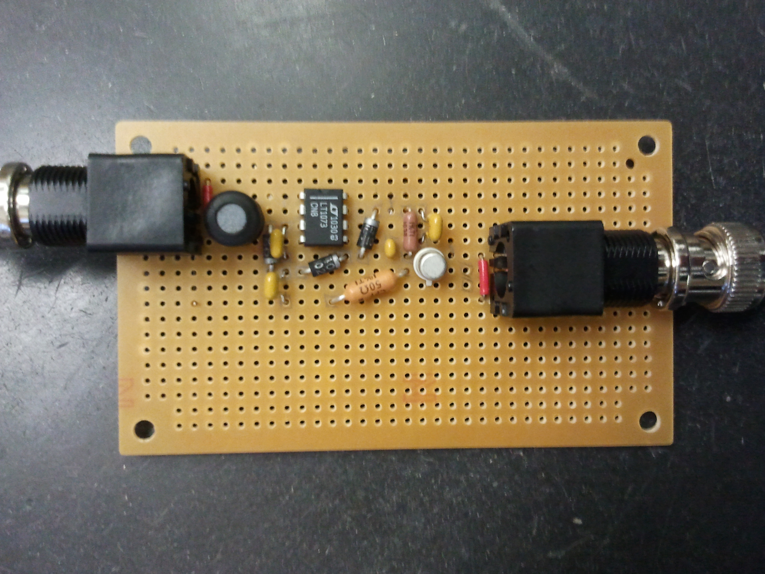
Pulse Generator
- Schematic of pulse generator
- Parts for pulse generator
- Picture of Pulse Generator
- Jon Kulakofsky's pulse generator fixing notes
- Pulser amplitude feedback amplifier
Presentations
- Gluex Collaboration Meeting May 2012
- Gluex Collaboration Meeting Feb. 2013
- Gluex Collaboration Meeting May 2013
- Gluex Collaboration Meeting Oct. 2013
- The Development and Construction of the Tagger Microscope for the GlueX Experiment (talk DNP-2013 Newport News, VA, 10/2013) - Alex Barnes