Used Fibers
Light Loss Along Length
I took the segments of wave guide that I had examined under microscope and exposed them to a green laser pointer with very little ambient light. The laser illuminated the wave guide and revealed the effects of surface damage. Areas with fissures, dust, or residue sparkled under the green light. This indicates significant light loss. Understanding light loss is key to the success of the tagger microscope.
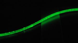
Figure 1: The effect of many surface imperfections becomes obvious when looking at a length of illuminated light guide. (Previously processed light guide. MFR: Saint Gobain BCF-98)
Surface Imperfections
Details of the damage are visible in these pictures.
Figure 2: In the upper right-hand third of the image are two parallel bands outlining a section of wave guide that seems brighter. This corresponds to the glue residue from the sticky labeling system. Other damage can also be seen.
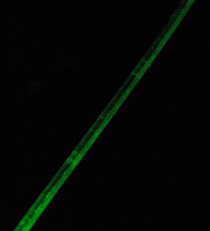
Figure 2: Detailed surface imperfections in previously processed light guide. (MFR: Saint Gobain BCF-98)
Figure 3: Nicks, gouges, and residues coat the length of the fiber, causing light loss everywhere.

Figure 3: Surface imperfections in previously processed light guide. (MFR Saint Gobain; BCF-98)
New Fibers
Clarity
Freshly cut light guide demonstrates remarkable clarity and minimal light loss. These images illustrate the smoothness of an undamaged surface.
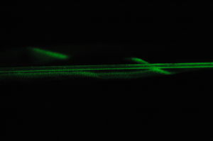
Figure4: Light Guide recently cut from spool shows exceptional clarity under laser light. (MFR Saint Gobain BCF-98)

Figure 5: Polished end of light guide away from light source, recently cut from spool. Long exposure reveals minimal light loss relative to end. (MFR Saint Gobain BCF-98)

Figure 6: Top view of light guide recently cut from spool. Uniform brightness indicates few surface abnormalities. (MFR Saint Gobain BCF-98)
Damage from Clamp
Other Surface Imperfections

Figure 10: Minimal surface imperfections visible near end of new light guide.

Figure 11: Imperfections along edge in new light guide.

Figure 12: Two sides of the wave guide are visible and minimal light loss is observed. Bright region due to laser angle.

.JPG)


