Difference between revisions of "Laser Images"
| Line 36: | Line 36: | ||
==Damage from Clamp== | ==Damage from Clamp== | ||
| − | The pictures below all reveal a band of damage near the clamped end of the spooled light guide. | + | The pictures below all reveal a band of damage near the clamped end of the spooled light guide. The damage goes all the way around the fiber and is only found at this point. I used extreme care when cutting the fiber and transporting them, and I do not believe these marks are from me. The implication of these images is important: if a weak foam-lined clamp (chip-clip style) can cause this damage, then one must wonder about other potential mishandling. I have observed hook-and-loop ties used to store fiber bundles, fibers laid across tables, fibers laid over sandpaper (quickly moved when pointed out), and fibers rubbing against other fibers. all of these scenarios are equally or more abrasive than the chip clip. I hypothesize that the materials coming into direct contact with the fibers are leaving the most damage, but that many, if not all, procedures for manipulating fibers are leaving marks. Pictures of the chip-clip and the hook-and-loop fasteners to come. |
<gallery> | <gallery> | ||
| − | File: Fast Shutter Clamp Damage DSC 0368.JPG|Figure 7 | + | File: Fast Shutter Clamp Damage DSC 0368.JPG|Figure 7 Damage to new light guide appears as a band around the end that was clamped during storage. |
| − | File:Cropped DSC 0059.JPG|Figure 8 | + | File:Cropped DSC 0059.JPG|Figure 8 Close up of damage near clamping site. |
| − | File:Cropped detail clamp damage DSC 0061.JPG|Figure 9 | + | File:Cropped detail clamp damage DSC 0061.JPG|Figure 9 Lower intensity laser allows the most severe scratches to be highlighted. |
</gallery> | </gallery> | ||
| + | |||
| + | In Figure 7, I shined a laser through the new light guide and used a paper bowl to block ambient light from the laser. To the left of the bowl, one sees bright spots on an otherwise dimly lit fiber. This corresponds to the position of the clamp. | ||
| + | |||
| + | Examining Figure 8 reveals several marks along the right half of the fiber. The leftmost striation is most well-defined, and beyond that the fiber does not spill light. I hypothesize that the clip may have been re-positioned, leaving other scratches, but the leftmost band was the farthest down the fiber that the clip was placed. Some of the poorly defined light loss from the right might simply be due to the position of the laser. | ||
| + | |||
| + | Figure 9 offers an alternate view with less ambient light. | ||
| + | |||
| + | It should be noted that the amount of light in the images varied because the laser intensity varied greatly. It would gradually get dimmer with time, until I removed the batteries and then put them back in. Interrupting contact with the batteries made the laser bright again. | ||
==Other Surface Imperfections== | ==Other Surface Imperfections== | ||
Revision as of 03:14, 29 January 2016
Used Fibers
Light Loss Along Length
I took the segments of wave guide that I had examined under microscope and exposed them to a green laser pointer with very little ambient light. The laser illuminated the wave guide and revealed the effects of surface damage. Areas with fissures, dust, or residue sparkled under the green light. This indicates significant light loss. Understanding light loss is key to the success of the tagger microscope.

Surface Imperfections
Details of the damage are visible in these pictures.
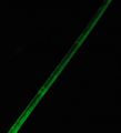
Figure 2: Detailed surface imperfections in previously processed light guide.

Figure 3: Surface imperfections in previously processed light guide.
.JPG)

Figure 2: In the upper right-hand third of the image are two parallel bands outlining a section of wave guide that seems brighter. This corresponds to the glue residue from the sticky labeling system. Other damage can also be seen.
Figure 3: Nicks, gouges, and residues coat the length of the fiber, causing light loss everywhere.
New Fibers
Clarity
Freshly cut light guide demonstrates remarkable clarity and minimal light loss. These images illustrate the smoothness of an undamaged surface.
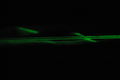
Figure4: Light Guide recently cut from spool shows exceptional clarity under laser light.
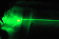
Figure 5: Polished end of light guide away from light source, recently cut from spool. Long exposure reveals minimal light loss relative to end.
Figure 6: Top view of light guide recently cut from spool. Uniform brightness indicates few surface abnormalities.

Damage from Clamp
The pictures below all reveal a band of damage near the clamped end of the spooled light guide. The damage goes all the way around the fiber and is only found at this point. I used extreme care when cutting the fiber and transporting them, and I do not believe these marks are from me. The implication of these images is important: if a weak foam-lined clamp (chip-clip style) can cause this damage, then one must wonder about other potential mishandling. I have observed hook-and-loop ties used to store fiber bundles, fibers laid across tables, fibers laid over sandpaper (quickly moved when pointed out), and fibers rubbing against other fibers. all of these scenarios are equally or more abrasive than the chip clip. I hypothesize that the materials coming into direct contact with the fibers are leaving the most damage, but that many, if not all, procedures for manipulating fibers are leaving marks. Pictures of the chip-clip and the hook-and-loop fasteners to come.
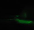
Figure 7 Damage to new light guide appears as a band around the end that was clamped during storage.
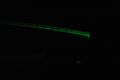
Figure 8 Close up of damage near clamping site.
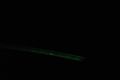
Figure 9 Lower intensity laser allows the most severe scratches to be highlighted.


In Figure 7, I shined a laser through the new light guide and used a paper bowl to block ambient light from the laser. To the left of the bowl, one sees bright spots on an otherwise dimly lit fiber. This corresponds to the position of the clamp.
Examining Figure 8 reveals several marks along the right half of the fiber. The leftmost striation is most well-defined, and beyond that the fiber does not spill light. I hypothesize that the clip may have been re-positioned, leaving other scratches, but the leftmost band was the farthest down the fiber that the clip was placed. Some of the poorly defined light loss from the right might simply be due to the position of the laser.
Figure 9 offers an alternate view with less ambient light.
It should be noted that the amount of light in the images varied because the laser intensity varied greatly. It would gradually get dimmer with time, until I removed the batteries and then put them back in. Interrupting contact with the batteries made the laser bright again.
Other Surface Imperfections
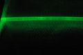
Figure 10: Minimal surface imperfections visible near end of new light guide.

Figure 11: Imperfections along edge in new light guide.
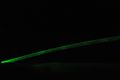
Figure 12: Two sides of the wave guide are visible and minimal light loss is observed. Bright region due to laser angle.


