Difference between revisions of "How to 3D Print"
| Line 12: | Line 12: | ||
==Setting up print files== | ==Setting up print files== | ||
The Autodesk Inventor Fusion software converts drawings to .stl files that can be 3D printed. To convert a drawing, open it with Inventor Fusion and follow the steps shown below. | The Autodesk Inventor Fusion software converts drawings to .stl files that can be 3D printed. To convert a drawing, open it with Inventor Fusion and follow the steps shown below. | ||
| − | [[Image:3D_1.jpg|center|thumb|300px|Figure 2: Click on the slanted letter | + | [[Image:3D_1.jpg|center|thumb|300px|Figure 2: Click on the slanted letter I in the top left corner.]] |
| − | |||
| − | |||
Revision as of 19:00, 4 March 2021
| Important Documents |
| 3D Printer Manual |
| PLA Filament MSDS |
| ABS Filament MSDS |
| UConn EHS 3D Printer Approval |
| [| Ben's Logbook] |
How to use the 3D Printer in lab 419
Setting up print files
The Autodesk Inventor Fusion software converts drawings to .stl files that can be 3D printed. To convert a drawing, open it with Inventor Fusion and follow the steps shown below.
A research group at Brookhaven National Laboratory ([1]) published results using a focused high-power UV laser to mill diamond via a process known as ablation. Lasers with wavelengths above the band gap of diamond (213 nm) can excite electrons between the diamonds carbon atoms from a bound state to an ionized state. The top 100 nm of the diamond surface at the focal spot is instantly vaporized, emitting a plume of carbon-based plasma normal to the surface of the diamond crystal. By scanning the diamond across the focal spot, a sequence of overlapping spots is built up that results in uniformly milling the sample surface. The short duration (10 ns) and short absorption length (50 nm) of the laser pulse ensure that the pulse energy is absorbed in the upper 100 nm of the diamond and does not result in deep energy deposition in the bulk of the crystal. Most importantly, this technique allows the diamond to be thinned deferentially, creating a central window of 20 microns thickness while retaining the full thickness around the edges for stiffness and support. This would never be possible with an abrasive technique. The laser ablation technique on diamond was developed extensively here at UConn by the author, using a Lambda Physik EMG 101 excimer laser operating at a wavelength of 193 nm as the light source. An XYZ computer controlled stage was constructed to sweep the diamond (under a vacuum of 600 mtorr) across the laser focus. The bulk diamond crystal before machining is typically of size 7.2 x 7.2 x 0.250 mm^3 . A series of laser pulses was applied to a rectangular region in the center of the diamond, milling a thin window down to the required thickness and leaving untouched a zone around the perimeter which is called the frame. The components of the experimental setup shown in Figure 1 are discussed in detail in the sections below.
Excimer Laser
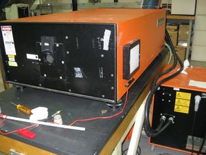
A Lambda Physik EMG 101 argon fluorine (ArF) excimer laser (shown in Figure 2) with an operating wavelength of 193 nm was used to ablate single-crystal CVD diamond. The laser is capable of delivering 120 mJ at a maximum repetition rate of 50 Hz and pulse duration of 20 nanoseconds. The pulse geometry is an asymmetrical flat top Gaussian with horizontal dimensions of 22 mm and vertical dimensions of 6 mm.
This particular laser shown in Figure 2 was over 30 years old when we first acquired it for the project. Much of my time (maybe too much :) ) has been spent restoring it so that it could maintain high energy levels for extended periods of time. All of my troubles are explicitly detailed in my logbooks which can be shared on request.
Ablation Software
Extensive software was written at UConn which converts surface measurements (taken with the Zygo) into a series of laser pulses and motor coordinates. The software uses a model of the beam spot and the Convolution Theorem to solve for the number and placement of laser pulses on the diamond so that it matches a end result specified by the user. The software used to create these "seq" files are listed below.
