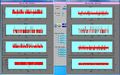
Active Collimator Installation Pictures
Active Collimator
The active collimator has been delivered to JLab by John Bartolotta. As of July 1, 2014 Alex Barnes is in charge of the assembly, testing, installation and analysis of the active collimator and the data collected with it.
- Alex's logbook can be viewed here.
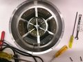
The active collimator is a beam position monitor that consists of a set of machined tungsten wedges placed in two concentric rings about a central hole of 5mm. When the beam hits a wedge it creates a current which can be readout through a preamplifier. Each ring consists of 4 wedges corresponding to +X, +Y, -X, and -Y directions.
Assembly
Components
- Screws
- brass
- round-headed
- 4-40 type
- 3/4 inch long
- Nuts
- brass
- 4-40 type
- 1/4 inch
- Drill bit used to drill out screw head
- 1/32 inch drill bit
- ream out the hole after using the drill bit to give it a taper
- the process is trial and error; drill and mount the RF connector until satisfied
- test connection by measuring the resistance from the RF signal connector to the screw
Pictures
Below are pictures of the assembling process
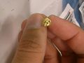
A machined screw for the RF connector.
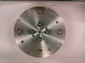
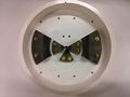
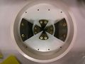
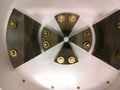
The back of the active collimator with only 4 installed wedges.
This is another view of the back of the active collimator with only 4 wedges installed.
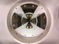
The active collimator with only 4 wedges installed. This was taken on the bench at JLab.
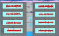
The spare wedges provided by FSU.
The fifth wedge has been installed.
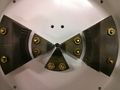
Closer shot of the fifth wedge. Notice how the wedge covers the hole slightly. This was noticed and fixed during the assembly process.
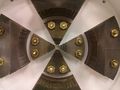
The sixth wedge has been installed in the active collimator.
The inner wedges have been adjusted to prevent blockage of the central hole.
The seventh wedge of the collimator has been installed.
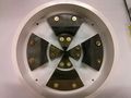
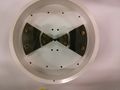
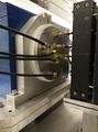
All wedges have been installed in the active collimator.
A closer view of all eight wedges of the active collimator.


Installation
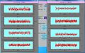
The active collimator has been installed in the collimator cave in Hall D. A shielding box was constructed out of plexi and placed above the active collimator.
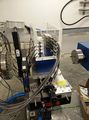
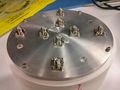
Active collimator preamps mounted and cabled inside of the plexi shielding.
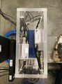
An overhead view of the active collimator preamps inside the shield box.
Active collimator installed and cabled.
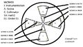
Scheme for active collimator cabling.


Initial noise measurements
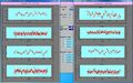
Initial noise measurements were recorded by Trent Allison on October 6, 2014. Below is a gallery of the waveforms from each wedge at each gain.
Noise with gain of 10e-6
Noise with gain of 10e-7
Noise with gain of 10e-8
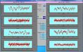
Noise with gain of 10e-9
Noise with gain of 10e-10
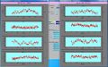
Noise with gain of 10e-11
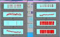
Noise with gain of 10e-12


Monitoring screens
Acronyms
- EPICS - Experimental Physics and Industrial Control System
- IOC - Input Output Controller (software component)
- PV - Process Variable in EPICS
- CSS - Control System Studio (application development environment)
- OPI file - Operator Interface file (application within CSS)
- AC - Active collimator
- Monticello - the MEDM main display gui that pops up when medm is started
- MEDM - Motif-based Editor and Display Manager (see here) used for graphical displays of active EPICS components by the accelerator, and accessed from the counting house by shift workers.
Active Collimator Naming Convention
- For EPICS PVs
- N9 corresponds to inner wedges
- N10 corresponds to outer wedges
- For Monticello plots
- I corresponds to inner wedges
- O corresponds to outer wedges
- Common to both EPICS and Monticello
- XP corresponds to X, plus
- XM corresponds to X, minus
- YP corresponds to Y, plus
- YM corresponds to Y, minus
List of EPICS PVs
Here are the waveform records with size of 8192, N9 are inner and N10 are outer:
- Inner
iochdcol:BPM:N9:raw_XPiochdcol:BPM:N9:raw_XMiochdcol:BPM:N9:raw_YPiochdcol:BPM:N9:raw_YM
- Outer
iochdcol:BPM:N10:raw_XPiochdcol:BPM:N10:raw_XMiochdcol:BPM:N10:raw_YPiochdcol:BPM:N10:raw_YM
These are the 16-bit count readings for individual plates that are always available and filtered down to ~1Hz (same order as above):
- Inner
IOCHDCOL:VMICADC1_1IOCHDCOL:VMICADC2_1IOCHDCOL:VMICADC3_1IOCHDCOL:VMICADC4_1
- Outer
IOCHDCOL:VMICADC1_2IOCHDCOL:VMICADC2_2IOCHDCOL:VMICADC3_2IOCHDCOL:VMICADC4_2
And the gains:
IPMHDACI_GainSubIPMHDACI_GAINXPIPMHDACI_GAINXMIPMHDACI_GAINYPIPMHDACI_GAINYMIPMHDACO_GainSubIPMHDACO_GAINXPIPMHDACO_GAINXMIPMHDACO_GAINYPIPMHDACO_GAINYM
Viewing AC waveforms in Monticello
- Connect to a gluon machine in the Hall D counting house
- In the terminal window type the command monticello
- In the Monticello screen, move the mouse to the BPM menu item and click the left-most button to reveal a pop-up menu. Select Hall D Active Collimator Diagnostics from the bottom of the popup menu. This will pop up a new window with the active collimator information.
- Make sure the following are selected
- iochdcol
- SEE Norm Ops
- FastSee Light On
- Update Mode Continuous
- To change the sampling rate go to the lower left corner of the GUI where it says “samples to avg (500kHz)” and change it to 64. This takes 500kHz and divides it by 64.
- Go to Raw Wire Data Graph button near the bottom and you can open the plots for the inner and outer plates. If the option ends in ‘I’ then it refers to the inner wedges, if it ends with ‘O’ it refers to the outer wedges.
- Within this new window you can change the axes ranges by right clicking on an axis. This will pop up a new window that has options for the min and max for each axis.
Accessing CSS AC GUI
- Connect to gluon05 in the Hall D counting house
- In the terminal window type the command css_gluon05
- This will open CSS as configured for gluon05. Only one profile instance can be run at a time
- css_gluon05 automatically opens the profile for gluon05 and includes the configurations required to view all of the Hall D GUIs
- If the tab “Main Action Bar” does not appear, do the following
- Click on Window->Open Perspective->Other
- Select CSS
- There should now be a button on the left labeled “CSS”. Click it and it will open the navigator
- Expand Hall-D and go to the very bottom and double-click “main_selection.opi”
- Once the main_selection.opi (has the name “Main Action Bar” on the tab) scroll down the the BEAM section and select Active Collimator. Click on it to open a new window
- This small GUI allows you to start/stop recording a ROOT file as well as a button to analyze the data. There is a window that shows where the ROOT file is being stored as well as the current size of the file and its size limit.
- To analyze the data, click the analyze button.
- The analyzer code can be found at ~hdops/acanalyzer
- When examining the root files, N9 are inner wedges, N10 are outer wedges.
Analysis
Analysis software can be found on the hdops account on the gluon machines in the directory ~/acanalyzer.
The beam position is determined using a difference over the sum of different wedges.