Fiber Dimension Statistics
This page was created by Andrew Sampino who's logbook for spring 2016 can be found here
The raw data for all of the reported statistics on this page can be found in this spreadsheet.
Average Width of Fibers
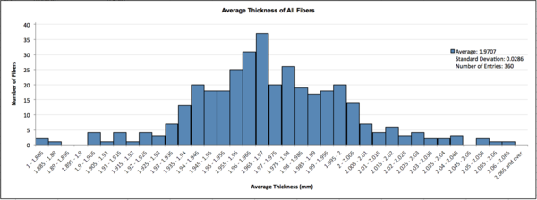
An analysis on the average width of the fibers was performed to check how many were over the maximum desired average width (2.03mm). The width of each fiber was measured at fifteen different points as a part of the cutting process. Histogram A shows the spread of average fiber width; almost all fibers meet the width specification with less than five percent exceeding the threshold width (2.03mm).
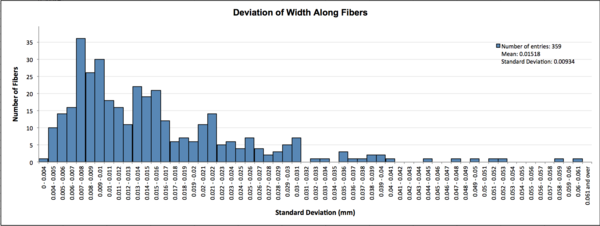
In order to gauge how accurately the averages represented the fibers, the standard deviations of the widths were also plotted. On histogram B the distribution of the standard deviation of width of each fiber is shown. Over ninety percent of the fibers' widths deviate by less than .03mm on average (1.5% of the maximum desired width). Considering histograms A and B, there are very few fibers that are too large or uneven to use.
Chimney End Measurements
The chimney end of the fibers is the most downstream end (away from fuse, near rubber band identifiers) where the fiber is inserted in a "chimney" used to hold it in place above a silicon photomultiplier for light collection. The chimneys have a maximum width requirement of 2.03mm. One hundred and twelve fibers, shown in this spreadsheet, have had their chimney ends measured as a part of an effort to produce bundles with a number of ideal dimensions for easy microscope installation. Of the one hundred and twelve, five fibers were found to have chimney ends that are too big.
Comparison Among Spools
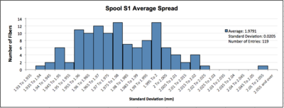
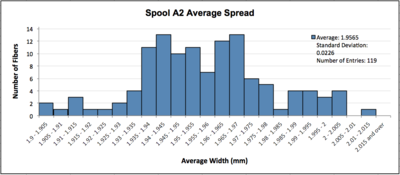
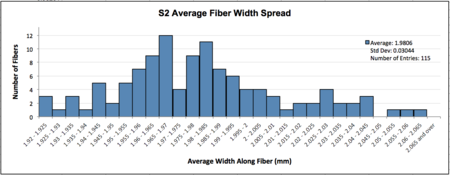
Every fiber was cut from one of four spools delivered by the manufacturer. An analysis of the widths of fibers from each spool was performed to determine if a significant difference in quality of fiber exists between them. The spools are named "A1", "A2", "S1", and "S2", where only six fibers were cut from spool A1 so it was omitted from the analysis due to a lack of representative data. As can be seen from histograms C through E, the average widths are within .025mm of each other indicating a consistent fiber size across spools. The standard deviation of spool S2 is about one and a half times as large as the other two showing substantially more change in the average width along fibers. This difference is still only on the order .01mm so no spool can be said to be significantly better or worse than the rest.
Fuse Widths
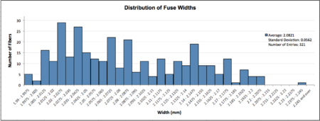
Fuse widths are the maximum thickness of a fiber at the fuse site between the scintillating fiber and the upstream end of the waveguide. The fusing process typically creates a slight bulge around the interface, which can interfere with bundling in the detectors. All fuse widths were measured as a part of the fusing procedure. Histogram F shows the distribution of fuse widths among all fused fibers (321 out of 360). The fibers average a fuse width of about 2.08mm, which puts sixty one percent of the fibers (196 fibers) over the originally planned the maximum width of (2.05mm). Using a more lenient maximum width of 2.15mm, only thirteen percent of fibers (43 fibers) fall out of the acceptable range. Even though many of the fibers have a large fuse joint, they shouldn't be counted as unusable since these joints can be sanded down without large losses of light yield.
