Difference between revisions of "Mapping diamond surfaces using interference"
| Line 26: | Line 26: | ||
Using the programming power of Matlab, we can solve our system of equations Mv=b, where M, v, and b are given below. | Using the programming power of Matlab, we can solve our system of equations Mv=b, where M, v, and b are given below. | ||
| + | {|width="80%" | ||
| + | |align="right"| | ||
<math>M = \begin{bmatrix} | <math>M = \begin{bmatrix} | ||
-1 & 1 & 1 & 0\\ | -1 & 1 & 1 & 0\\ | ||
| Line 32: | Line 34: | ||
0 & Z_2^{-1} e^{ik_2a} & Z_2^{-1} e^{-ik_2a} & -Z_1^{-1} e^{-ik_1a} | 0 & Z_2^{-1} e^{ik_2a} & Z_2^{-1} e^{-ik_2a} & -Z_1^{-1} e^{-ik_1a} | ||
\end{bmatrix}</math> | \end{bmatrix}</math> | ||
| + | |align="center"|(1) | ||
| + | |} | ||
| + | |||
<math> v = \begin{bmatrix} E_r\\ E_f\\ E_b\\ E_t\end{bmatrix}</math> | <math> v = \begin{bmatrix} E_r\\ E_f\\ E_b\\ E_t\end{bmatrix}</math> | ||
Revision as of 16:48, 14 March 2007
This page represents a ongoing project dealing with using interference patterns to map the surface of a diamond wafer. Since this is my first page, you'll have to excuse any blatant errors that I do not pick up on immediately. Currently this page will represent my work with Dr. Richard Jones on an approximation to the beam splitter featured in the Michelson interferometer. I will start by giving a brief introduction to electromagnetic radiation, then move on to the approximation itself (including graphs,etc.). I will hopefully have this up and running by next Wednesday.
INTERFERENCE AND LIGHT WAVES
Light (electromagnetic radiation)
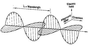
is comprised of an temporally and spatially oscillating electric and magnetic field components. These components are orthogonal to each other as well as to the direction of propagation given by the Poynting vector. Wave equations for the electric and magnetic fields can be derived using Maxwell's Equations.
Something about plane wave solutions here.
Electromagnetic waves also have the property that they interfere.
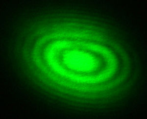
Like interfering mechanical waves, EM waves can interfere destructively or constructively depending on the phase difference between the two waves. In order for this to occur, the light waves must be traveling in the same direction, be of the same wavelength and have a constant phase with respect to each other. A picture of EM wave interference is shown at right.
INTERFEREOMETRY AND THE MICHELSON INTERFEROMETER
Interferometry is the splitting of light beams into two or more paths and the recombining of those different beams to measure difference in optical path length and refractive index [1] via interference fringes that form as a result of the recombined beams.
The Michelson interferometer
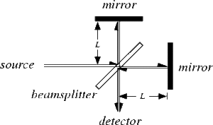
was invented by Albert Michelson in 1882 “to detect a change in the velocity of light due to the motion of the [ether]” [2]. The findings of Michelson's experiment eventually went on to support Einstein's theory of relativity. Add something here describing the parts of the Michelson interferometer.
For our experiment we will be utilizing the fringes of the Michelson interferometer to gather information about the topology of synthetic diamond wafers. In order to be able to utilize a computer program to analyze the data gathered from the Michelson interferometer, we start with an approximation of the beam splitter present at the center of the interferometer. We know that the beam splitter is comprised of a thin layer of a conducting substance present on one side of a thin piece of optical glass. When a beam of light is incident on the beam splitter, a fraction of the photons travel through to the other side of the splitter and the remaining photons reflected. Here we consider wavelengths at which the fraction of the beam absorbed by the mirror is negligible.
Using our knowledge of electric and magnetic fields in conductors and Maxwell's Equations, we can create a simple model of the beam splitter with a light wave at normal incidence. We are interested in finding two main quantities in this model: the thickness of the conducting film and the phase shift that occurs at the mirror surface. Need more here about the calculations we did.
Using the programming power of Matlab, we can solve our system of equations Mv=b, where M, v, and b are given below.
|
|
(1) |
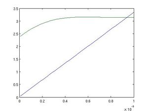
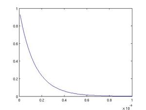
Using Matlab we were able to extract information about the desired depth of the conducting film and the phase shift that occurred when the light wave traveled through the the film.
Our graphs dislpaying phase shift versus depth
and amplitude versus depth
Steel "Interferometry"
References
1. C. Candler, Modern Interferometers, Addison-Wesley, 1982, p.9.
2. ibid, p.110.


