Difference between revisions of "Calibration Device for Scintillators"
Jump to navigation
Jump to search
(→To Do) |
|||
| Line 28: | Line 28: | ||
== Belt System == | == Belt System == | ||
*Stepper motor with micro controller stands stationary on one end and calibration device would be connected to a slide rail system for stability[[File:Gears 01.gif|thumb|Clamping Plate Setup http://www.polytechdesign.com/images/gears_01.gif]] | *Stepper motor with micro controller stands stationary on one end and calibration device would be connected to a slide rail system for stability[[File:Gears 01.gif|thumb|Clamping Plate Setup http://www.polytechdesign.com/images/gears_01.gif]] | ||
| − | *We need to find something that is low cost but is accurate enough to be stopped at each fiber array block | + | *We need to find something that is low cost but is accurate enough to be stopped at each fiber array block. Because the intended light source for calibration is most likely going to have a wide range, the step size does not have to be too small. |
*For support: Overhead Enclosed-Track Conveyor Bracket, linear guide rail | *For support: Overhead Enclosed-Track Conveyor Bracket, linear guide rail | ||
[[File:linear motion setup.png|thumb|Linear Motion Setup]] | [[File:linear motion setup.png|thumb|Linear Motion Setup]] | ||
==== Motor ==== | ==== Motor ==== | ||
| − | * | + | *LinEngineering 1.8 Degree Motor 'WO-4118S-01' was found to be appropriate and cost effective. [http://www.linengineeringstore.com/products/product_detail.aspx?proID=2] |
| + | |||
| + | ===Step Size=== | ||
| + | *With a LinEngineering 1.8 Degree Motor and a radius of .5" for the pulley, the step size would be 0.005" or 0.127mm which is well within a 2mm scintillator. | ||
==To Do== | ==To Do== | ||
Revision as of 21:08, 25 January 2011
- The objective is to create a linear motion device that will calibrate a set array of scintillators using light pulses
Ideas
- Printer disassembly and take-over of printer head linear motion through use of parallel port programming with C
- Worm gear connected to DC motor with micro controller set up
- Linear Rail system
- Stepper Motor Belt System
Printer's Linear Motion
- Disassembled printer casing
- Installed cygwin on computer for C interface and read up on programming language C
- Investigated Computer Numerical Control but found it was not useful for this application
- Investigated serial port programming and the use of Printer Control Language on an HP printer click here for documentation on PCL
Parallel Port Programming
- Interfacing directly to the printer proved very challenging . For help, click here.
- Unsuccessfully accessed printer
Worm Gear
- Spinning a long grooved metal cylinder gear requires a lot of torque
- Minimal support for head motion
- DC motor with time steps is not as effective as stepper motor
Rail System
- Has internal motion control
- very costly
- possibly too heavy duty for this application
Belt System
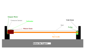
- Stepper motor with micro controller stands stationary on one end and calibration device would be connected to a slide rail system for stability
 Clamping Plate Setup http://www.polytechdesign.com/images/gears_01.gif
 - We need to find something that is low cost but is accurate enough to be stopped at each fiber array block. Because the intended light source for calibration is most likely going to have a wide range, the step size does not have to be too small.
- For support: Overhead Enclosed-Track Conveyor Bracket, linear guide rail
Motor
- LinEngineering 1.8 Degree Motor 'WO-4118S-01' was found to be appropriate and cost effective. [1]
Step Size
- With a LinEngineering 1.8 Degree Motor and a radius of .5" for the pulley, the step size would be 0.005" or 0.127mm which is well within a 2mm scintillator.
To Do
- Tightening Mechanism for belt
- Pin for gear
- Find gear diameters
- Mount for Pin
- Motor Mount
- Learn to use the controller
- Find pressure sensor for zero marker
- Assembly
- Deign light source on top of cart
