Difference between revisions of "Calibration Device for Scintillators"
| (One intermediate revision by the same user not shown) | |||
| Line 8: | Line 8: | ||
''' | ''' | ||
| − | ===Project Proposal=== | + | ===Project Proposal and Overview=== |
| − | + | The confinement of quarks and gluons within the hadron has been declared one of the top ten physics mysteries of the century. Quarks, along with leptons, are the smallest known building blocks of our universe, however scientists have yet to isolate one. Quarks and anti-quarks exist only in bundles known as hadrons, bound tightly together by the force-carrier particles gluons. The reason for the massive strength of such bonds remains unknown, and open for exploration. The field of Quantum Chromodynamics designates such a force the “Color Force”, further explaining that quarks and gluons carry a “color charge” (Red, Blue, Green, AntiRed, AntiBlue, or AntiGreen). As quarks and gluons frantically interact and transfer color charges, the net color of any given hadron remains colorless. When quarks pull away, the color force merely stretches and grows stronger, forever confining the quarks and gluons. The color force is a fundamental interaction, the source of even the strong interaction, and thus an understanding of the gluonic field would unveil an entirely new realm of physics that is driving the world around us. | |
| − | |||
| − | |||
| − | |||
| + | The GlueX Experiment, centered in Jefferson Lab, Virginia, is devoted to understanding the gluonic field by mapping the spectrum of the exotic hybrid meson. When the gluonic field is excited, hybrid mesons (hadrons composed of quark-antiquark pair and valence gluon) with exotic JPC quantum numbers are produced and these can be an indirect probe of the gluonic field. The experiment utilizes a particle accelerator to direct a 12 GeV electron beam at a diamond wafer, splitting it into a 9 GeV linear polarized photon beam and 3 GeV electron beam via coherent bremsstrahlung radiation. Known as photoproduction, this process produces virtual vector mesons, some with exotic JPC. The photon beam enters the solenoid detector, where the meson decays are analyzed and reconstructed. The scattered electrons, bent by a magnetic field, travel through a tagger microscope guided by optical fibers. Because bend radius corresponds to energy, the fiber paths indicate energy level. Silicon photomultiplier sensors are then able to “tag” the electrons with an initial momentum, and associate an energy with the corresponding photon. This tagger microscope provides important information for meson reconstruction that must be accurate. There is not, however, a current means for ensuring this. | ||
| + | |||
| + | For my research I will be designing and building a calibration device for the tagger microscope. The device will consist mechanically of a metal track with two flanged timing pulleys at each end and a timing belt connecting them. A cart will be pulled horizontally by the belt, which is driven by a Lin-Engineering 1.8 degree stepper motor. The motor is controlled by a program which I have written in LabVIEW, along with a DAQ card, R208 microstep driver, and quadrature rotary encoder. Extending down from the moving cart will be a light pulser that will hover over the fiber bundles and flash light to calibrate them. More specifically, two methods are being explored for light distribution: (1) Waveshifting fibers and (2) Mylar reflection. Waveshifting fibers, which when placed over the fiber bundles would illuminate only to UV light, would be effective but costly. Mylar reflection, in which a laser diode uses the mylar mirror to reflect light into the fiber bundles, would be cheaper but includes problems such as refraction, interference, and the fibers’ narrow window of light acceptance. I am currently writing a Matlab program to explore the feasibility of this second method. | ||
| + | |||
| + | A mechanized calibration device is a small, but instrumental, element of the GlueX experiment. Unable to access the microscope while it’s running, we nevertheless need to know that we can trust its results. The results of this experiment are expected to increase the knowledge of Quantum Chromodynamics by several orders of magnitude. The scope includes energy advances, as an understanding of the confinement of antiquarks could help us harness antimatter. From here, the potential extends from renewable energy to space travel. But fundamentally, this experiment seeks to expose an unknown element of physics, and I hope to contribute. | ||
| + | |||
| + | ===Mechanical Setup=== | ||
| + | ====Track==== | ||
| + | A linear aluminum track will be used as the framework for this device. About a meter and a half in diameter, the track has ridges that allow the robot cart to ride along it. [[Image:device.png]] | ||
== Previous Work -- John Turner == | == Previous Work -- John Turner == | ||
Latest revision as of 18:33, 28 June 2012
Atoms contain nuclei that are made up of protons and neutrons which are comprised of quarks. These quarks are confined inside protons and neutrons by powerful bonds that are generated by the strong nuclear force of attraction between them. Particle physicists visualize these bonds as “channels” that form between the quarks, over which they continuously exchange virtual particles known as gluons. A new particle physics experiment, GlueX, is being constructed at the Thomas Jefferson National Accelerator Facility (Jefferson Lab) in Newport News Virginia, with the capability to excite the gluonic bonds between quarks and study their dynamics.
To do this, the GlueX experiment requires a beam of polarized light (photons) with a very short wavelength, in the gamma ray spectrum. This beam of polarized photons is created by passing high-energy electrons from the Jefferson Lab accelerator through an oriented diamond crystal, such that they emit coherent bremsstrahlung radiation. The energy of each photon in the beam is “tagged” by detecting the electron that produced it in a scintillating fiber array called the tagging microscope.
To calibrate the tagging microscope, a source mounted on a linear motion stage has been designed and fabricated. The design, assembly and initial tests of this system is described.
Active Project -- Emily Briere
Project Proposal and Overview
The confinement of quarks and gluons within the hadron has been declared one of the top ten physics mysteries of the century. Quarks, along with leptons, are the smallest known building blocks of our universe, however scientists have yet to isolate one. Quarks and anti-quarks exist only in bundles known as hadrons, bound tightly together by the force-carrier particles gluons. The reason for the massive strength of such bonds remains unknown, and open for exploration. The field of Quantum Chromodynamics designates such a force the “Color Force”, further explaining that quarks and gluons carry a “color charge” (Red, Blue, Green, AntiRed, AntiBlue, or AntiGreen). As quarks and gluons frantically interact and transfer color charges, the net color of any given hadron remains colorless. When quarks pull away, the color force merely stretches and grows stronger, forever confining the quarks and gluons. The color force is a fundamental interaction, the source of even the strong interaction, and thus an understanding of the gluonic field would unveil an entirely new realm of physics that is driving the world around us.
The GlueX Experiment, centered in Jefferson Lab, Virginia, is devoted to understanding the gluonic field by mapping the spectrum of the exotic hybrid meson. When the gluonic field is excited, hybrid mesons (hadrons composed of quark-antiquark pair and valence gluon) with exotic JPC quantum numbers are produced and these can be an indirect probe of the gluonic field. The experiment utilizes a particle accelerator to direct a 12 GeV electron beam at a diamond wafer, splitting it into a 9 GeV linear polarized photon beam and 3 GeV electron beam via coherent bremsstrahlung radiation. Known as photoproduction, this process produces virtual vector mesons, some with exotic JPC. The photon beam enters the solenoid detector, where the meson decays are analyzed and reconstructed. The scattered electrons, bent by a magnetic field, travel through a tagger microscope guided by optical fibers. Because bend radius corresponds to energy, the fiber paths indicate energy level. Silicon photomultiplier sensors are then able to “tag” the electrons with an initial momentum, and associate an energy with the corresponding photon. This tagger microscope provides important information for meson reconstruction that must be accurate. There is not, however, a current means for ensuring this.
For my research I will be designing and building a calibration device for the tagger microscope. The device will consist mechanically of a metal track with two flanged timing pulleys at each end and a timing belt connecting them. A cart will be pulled horizontally by the belt, which is driven by a Lin-Engineering 1.8 degree stepper motor. The motor is controlled by a program which I have written in LabVIEW, along with a DAQ card, R208 microstep driver, and quadrature rotary encoder. Extending down from the moving cart will be a light pulser that will hover over the fiber bundles and flash light to calibrate them. More specifically, two methods are being explored for light distribution: (1) Waveshifting fibers and (2) Mylar reflection. Waveshifting fibers, which when placed over the fiber bundles would illuminate only to UV light, would be effective but costly. Mylar reflection, in which a laser diode uses the mylar mirror to reflect light into the fiber bundles, would be cheaper but includes problems such as refraction, interference, and the fibers’ narrow window of light acceptance. I am currently writing a Matlab program to explore the feasibility of this second method.
A mechanized calibration device is a small, but instrumental, element of the GlueX experiment. Unable to access the microscope while it’s running, we nevertheless need to know that we can trust its results. The results of this experiment are expected to increase the knowledge of Quantum Chromodynamics by several orders of magnitude. The scope includes energy advances, as an understanding of the confinement of antiquarks could help us harness antimatter. From here, the potential extends from renewable energy to space travel. But fundamentally, this experiment seeks to expose an unknown element of physics, and I hope to contribute.
Mechanical Setup
Track
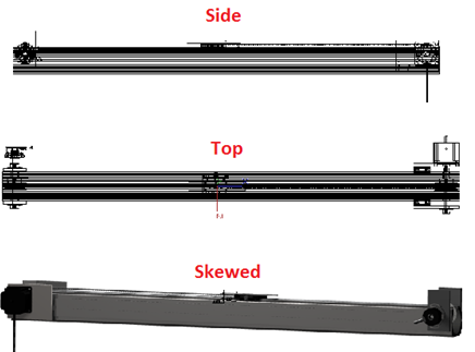
A linear aluminum track will be used as the framework for this device. About a meter and a half in diameter, the track has ridges that allow the robot cart to ride along it. 
Previous Work -- John Turner
Ideas
- Printer disassembly and take-over of printer head linear motion through use of parallel port programming with C
- Worm gear connected to DC motor with micro controller set up
- Linear Rail system
Stepper Motor Belt System was chosen
Printer's Linear Motion
- Disassembled printer casing
- Installed cygwin on computer for C interface and read up on programming language C
- Investigated Computer Numerical Control but found it was not useful for this application
- Investigated serial port programming and the use of Printer Control Language on an HP printer documentation on PCL
Parallel Port Programming
- Interfacing directly to the printer proved very challenging [1]
- Unsuccessfully accessed printer
Worm Gear
- Spinning a long grooved metal cylinder gear requires a lot of torque
- Minimal support for head motion
- DC motor with time steps is not as effective as stepper motor
Rail System
- Has internal motion control
- Very costly
- Too heavy duty for this application
Belt System
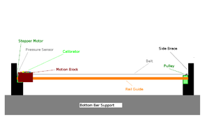
- Stepper motor with micro controller stands stationary on one end and calibration device would be connected to a slide rail system for stability
 Clamping Plate Setup http://www.polytechdesign.com/images/gears_01.gif
 - We need to find something that is low cost but is accurate enough to be stopped at each fiber array block. Because the intended calibration source is most likely going to have a wide range, the step size does not have to be too small.
- For support: Overhead Enclosed-Track Conveyor Bracket, linear guide rail
Beam Deflection
- The deflection at the center of the slide rail is calculated using a simply end supported beam as a model with beam deflection equations considering the weight of the bar and the weight of the cart. The maximum deflection was calculated as not exceeding 6um, well within the limit for our usage.
Motor
- LinEngineering 1.8 Degree Motor 'WO-5718X-05E' was found to be appropriate and cost effective. [2]
- With a LinEngineering 1.8 Degree Motor and a radius of .5" for the pulley, the step size would be 0.005" or 0.127mm which is well within a 2mm scintillator.
Electronics
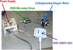
- To operate the linear motion stage, a series of electronics is set up that works together to move the pulley system. First a computer program built with Labview was created to communicate with the Digital to Analog Controller(DAC) via USB. The DAC has pin-outs arranged similarly to a serial port, that control the driver. The R208 microstep driver has various wires connected to the DAC. When the circuits are opened and closed via the Labview program, the stepper motor steps forward or backward. From the driver, the 5V logic power wire is connected to the 5V output on the DAC and the 24V, 2 Amp power driver wire is connected to the power supply. The logic ground and power ground are also connected to the power supply ground. The stepper motor in use is a 1.8 degree high-torque model with a four wire connection.
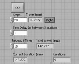
- The user can select a left or right direction, how many steps per interval, the number of iterations and the time delay between iterations. The program tracks the current location of the rail carriage based on the number of degrees rotated.
Structure
- The main feature of the linear motion stage is the heavy duty optical rail the carriage moves along. Two pulley mounts designed in Turbocad and fabricated out of aluminum are used to hold up the pulleys and attach the stepper motor. The mounts are fasted to the optical rail using bolts attached to rail clamps. A belt is placed connecting the two pulleys and is tightened using the rail clamps on the optical bar. The rail carriage that will house the calibration source is attached to the belt via a metal clamp. The linear motion stage will not only be effective moving precision distances to calibrate the fiber array, but it is rigid enough to be used as a structural beam in the construction of the tagger microscope.
To Do
- Integrate rotary encoder in labview program
- Further investigation needs to be done concerning the type of source and mounting setup needed for the calibrator. The final dimensions of the tagger microscope is not yet known, so further work has to be done to establish a final location for this optical rail and calibration arm. Specifically with regards to the source, the frequency and power of the source must be determined, as well as the focusing mechanism.


