Difference between revisions of "Fiber Testing Procedure"
| (7 intermediate revisions by 3 users not shown) | |||
| Line 1: | Line 1: | ||
| − | |||
| − | |||
| − | |||
It is important to determine light yield of each fiber before shipment to Jefferson Lab. In order to do this, light yield tests will be performed on each fiber in our dark box using a red laser diode on a pulsing circuit. The setup of the fibers is very important, as any offset fibers could give an inaccurate result. It is also important that procedure is followed to prevent damage to electronics. | It is important to determine light yield of each fiber before shipment to Jefferson Lab. In order to do this, light yield tests will be performed on each fiber in our dark box using a red laser diode on a pulsing circuit. The setup of the fibers is very important, as any offset fibers could give an inaccurate result. It is also important that procedure is followed to prevent damage to electronics. | ||
| − | '''If the electronics are powered and the dark box is open, the | + | '''If the electronics are powered and the dark box is open, the silicon photo-multipliers (SiPMs) WILL be damaged''', so it is very important to make sure electronics are off before the dark box is opened. |
==Fiber QA Troubleshooting== | ==Fiber QA Troubleshooting== | ||
| Line 14: | Line 11: | ||
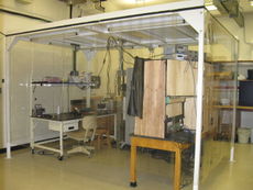
[[File:LH-FiberTesting-CleanRoom.jpg|thumb|right|upright|The ventilated clean room with a workbench, the dark box, and all necessary electronics.]] | [[File:LH-FiberTesting-CleanRoom.jpg|thumb|right|upright|The ventilated clean room with a workbench, the dark box, and all necessary electronics.]] | ||
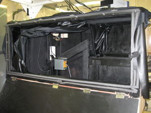
[[File:LH-FiberQA_Darkbox.jpg|thumb|left|The darkbox open and empty. The black plastic is pulled back and suspended with wires so you can see both sides: the pulser side and the chimney side.]] | [[File:LH-FiberQA_Darkbox.jpg|thumb|left|The darkbox open and empty. The black plastic is pulled back and suspended with wires so you can see both sides: the pulser side and the chimney side.]] | ||
| − | *Before taking any fibers out of the dark room, open the [https://docs.google.com/a/uconn.edu/spreadsheets/d/1T4NUSQO_keT0QckCx4rWlbMW7Yot4vb-Z1eqrM1l94k|Fiber QA] Google Doc. Each bundle has a separate tab which you can view the alignments required for each run. | + | *Before taking any fibers out of the dark room, open the [https://docs.google.com/a/uconn.edu/spreadsheets/d/1T4NUSQO_keT0QckCx4rWlbMW7Yot4vb-Z1eqrM1l94k/|Fiber QA] Google Doc. Each bundle has a separate tab which you can view the alignments required for each run. |
| − | *Before selecting fibers from their dark room, don a pair of powder free gloves and place the popsicle stick with the testing clamps at the table you will be working. Also grab 3 kapton strips from the kapton strip box along with accompanying bolts and washers. | + | *Before selecting fibers from their dark room, don a pair of powder free gloves and place the clean popsicle stick with the testing clamps at the table you will be working. Also grab 3 kapton strips from the kapton strip box along with accompanying bolts and washers. |
*Note which fibers are to be tested during the run and take only those fibers out of the dark room. The fibers not attached to a popsicle stick are sorted by bending bundle name. | *Note which fibers are to be tested during the run and take only those fibers out of the dark room. The fibers not attached to a popsicle stick are sorted by bending bundle name. | ||
| − | * | + | *On a large table/workbench, sort the fibers into the 6 columns of 5 fibers. |
| − | |||
| − | * | + | *Start with one column and put the fibers from that column in their appropriate order per the matrix on the spreadsheet. It is best to use the bundling tool for this process and support the fiber using the Bundling Support. Be sure the fiber ends are secured and not bent at the end. |
| − | * | + | *Continue this process with the remaining columns. |
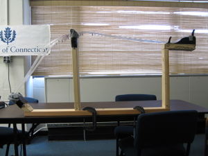
| − | + | [[File:LH-FiberQA_BendingSupport.jpg|thumb|center|The bending support constructed to aid in the process of bundling for Fiber QA.]] | |
| − | *Once the fibers are in the order they belong, | + | *Once the fibers are in the order they belong, place them on the popsicle stick and secure the metal clamp and the downstream kapton strip. |
**This step will take two people. One person should place the fibers, while the other should hold them in place once they are placed. This way fibers will stay in their appropriate positions. | **This step will take two people. One person should place the fibers, while the other should hold them in place once they are placed. This way fibers will stay in their appropriate positions. | ||
| − | * | + | *Tighten the second kapton strip over the fibers, making sure the fibers do not tangle and are in the two 3x5 orientations. The kapton strip should be tight enough that the fibers don't lose orientation but should slide through. |
| − | |||
| − | |||
| − | |||
| − | |||
| − | |||
| − | |||
| − | |||
| − | |||
| − | * | + | *Using the end of the bundling tool or any other flat surface, make the upstream 15 fibers flush to the edge of the popsicle stick. Once this is set, cut a small portion of wooden stirrer and place it under the 1st kapton strip. Pull the kapton strip tight and secure it. You should be done securing the upstream 15 fibers. |
| − | * | + | *With the upstream set of 15 secure, it's much easier to secure the second 15 fibers. Loosen the middle kapton strip and using the same process as with the upstream 15 fibers, make the downstream 15 fibers flush against the edge of the popsicle stick. Once flush, put another portion of wood stirrer under the middle kapton strip. Pull down the kapton strip tight and secure it in place. |
| − | * | + | *To add paper spacers, use the cardstock and cut them into pieces that are about the width of 3 fibers. |
| − | |||
| − | |||
| − | * | + | *Place paper spacers between the rows and columns of each set of 15. They should be at the beginning of the S-bends and after the middle kapton strip. |
| − | |||
| − | * | + | *Once both upstream kapton strips are tight and have the wood stirrer, place a wood stirrer under the last downstream kapton strip, pull it tight and secure it. |
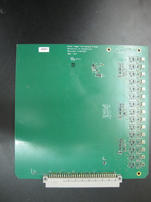
[[File:LH-FiberQA_Preamp.jpg|thumb|right|Preamp board 00001. The 15 SiPMs are across the top. Only trained lab technicians should handle the preamp boards!]] | [[File:LH-FiberQA_Preamp.jpg|thumb|right|Preamp board 00001. The 15 SiPMs are across the top. Only trained lab technicians should handle the preamp boards!]] | ||
| − | *'''Check that all electronics are off before opening the dark box! Have a grad student or lab technician remove the preamp board after opening the dark box.''' Carefully | + | *'''Check that all electronics are off before opening the dark box! Have a grad student or lab technician remove the preamp board after opening the dark box.''' Carefully open the main dark box opening and dock the popsicle stick into place by tightening the two screws underneath the popsicle stick to secure it into place. The wood has been depressed in the place where the popsicle stick should be. '''Do not modify the position of the pulsar at any point during the loading process!''' |
| − | |||
*Cover the fibers with the black cloth. Be careful not to cover the path from the mirror to the off-set bundle! | *Cover the fibers with the black cloth. Be careful not to cover the path from the mirror to the off-set bundle! | ||
| + | **Use the mirror tool to see the scintillating fibers. | ||
*Let the black plastic divider down and Velcro the top opening shut so no light passes from the pulsar side to the SiPM side of the dark box. | *Let the black plastic divider down and Velcro the top opening shut so no light passes from the pulsar side to the SiPM side of the dark box. | ||
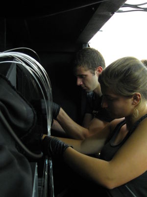
[[File:LH-FiberQA_FibersChimney.jpg|thumb|left|Marco and Suki carefully placing the fibers into their respective chimneys.]] | [[File:LH-FiberQA_FibersChimney.jpg|thumb|left|Marco and Suki carefully placing the fibers into their respective chimneys.]] | ||
*Guide the fiber ends over the edge and using the Google Document, place the fibers into the chimney in the correct order. Channel 1 on each chimney is the channel closest to the backplane. | *Guide the fiber ends over the edge and using the Google Document, place the fibers into the chimney in the correct order. Channel 1 on each chimney is the channel closest to the backplane. | ||
| − | **Check that each fiber is flush against the chimney edge using | + | **Check that each fiber is flush against the chimney edge using touch, and finally, visually inspect using the light/mirror. |
**If any fibers are not flush against the edge, re-do the previous step. | **If any fibers are not flush against the edge, re-do the previous step. | ||
| − | *'''Have a lab technician check the fibers at this step.''' The fibers | + | *'''Have a lab technician check the fibers at this step.''' The fibers must not be too far into the chimneys or else they will damage the SiPMs when the board is replaced. |
| − | *'''A grad student or lab technician''' must put the SiPM board back into place. Do not | + | *'''A grad student or lab technician''' must put the SiPM board back into place. Apply even pressure to the ends of the preamp boards until they are in place. Do not push so hard that it is bending the backplane. If needed, just place the preamp support end and screw it into the preamp supports until they are flush. |
| − | *Close the main dark box opening and ensure that it is light sealed. | + | *Close the main dark box opening and lock it tight to ensure that it is light sealed. |
| − | *Turn on the power supply for the pulser and the op-amp first. Check that the voltages remain constant at 1.5 V and -10 V. Next turn on the power supply for the pre-amps | + | *Turn on the power supply for the pulser and the op-amp first. Check that the voltages remain constant at 1.5 V and -10 V. Next turn on the 60 V power supply for the pre-amps followed by the remaining power supplies. When turning off the voltages make sure the 60 V power supply is the last one turned off. |
| + | **Watch the control board's power supply current. If it exceeds. 0.38 amps, let a lab technician know immediately! The power supplies may have turned on in the wrong order or the pins on the backplane are making contact through the gasket. | ||
{|style="margin: 0 auto;" | {|style="margin: 0 auto;" | ||
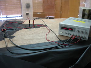
|[[File:LH-FiberQA_PulserPower.jpg|thumb|center|A view of the power supply powering the pulser and op-amp.]] | |[[File:LH-FiberQA_PulserPower.jpg|thumb|center|A view of the power supply powering the pulser and op-amp.]] | ||
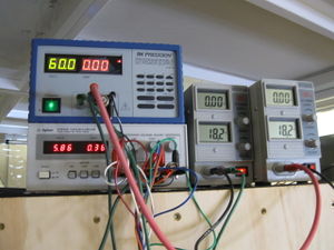
| Line 76: | Line 62: | ||
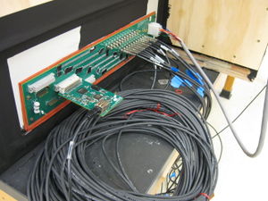
|[[File:LH-FiberQA_Backplane.jpg|thumb|center|A view of the backplane.]] | |[[File:LH-FiberQA_Backplane.jpg|thumb|center|A view of the backplane.]] | ||
|} | |} | ||
| + | *Have a lab technician or grad student check the VBias after about 15-20 minutes of the control board being on. | ||
*Start the run from the gryphn.uconn.edu web address. | *Start the run from the gryphn.uconn.edu web address. | ||
| − | **It takes 7-8 minutes from the time the run begins to complete. If the run does not finish in this time, something has gone wrong. Notify a grad student. | + | **It takes 7-8 minutes from the time the run begins to complete. If the run does not finish in this time, something has gone wrong. Notify a grad student or lab technician. |
| + | *Input the run from the data into the Google docs spreadsheet. Note the time of request and run, as well as the people involved in the run. | ||
Latest revision as of 16:43, 18 December 2015
It is important to determine light yield of each fiber before shipment to Jefferson Lab. In order to do this, light yield tests will be performed on each fiber in our dark box using a red laser diode on a pulsing circuit. The setup of the fibers is very important, as any offset fibers could give an inaccurate result. It is also important that procedure is followed to prevent damage to electronics.
If the electronics are powered and the dark box is open, the silicon photo-multipliers (SiPMs) WILL be damaged, so it is very important to make sure electronics are off before the dark box is opened.
Fiber QA Troubleshooting
We made our testing darkbox from scratch so we had to configure electronics and troubleshoot issues with the Fiber QA Procedures. You can read the details of these effors on the Fiber QA Troubleshooting page, but they are summarized below:
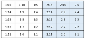
Fibers will be issued a new name after QA in the form of a bundle number, followed by a colon and then a fiber number. The diagram below shows how the fibers are positioned as viewed within the fibers, looking from the light guides out through the SciFis.
Procedure
- Before taking any fibers out of the dark room, open the QA Google Doc. Each bundle has a separate tab which you can view the alignments required for each run.
- Before selecting fibers from their dark room, don a pair of powder free gloves and place the clean popsicle stick with the testing clamps at the table you will be working. Also grab 3 kapton strips from the kapton strip box along with accompanying bolts and washers.
- Note which fibers are to be tested during the run and take only those fibers out of the dark room. The fibers not attached to a popsicle stick are sorted by bending bundle name.
- On a large table/workbench, sort the fibers into the 6 columns of 5 fibers.
- Start with one column and put the fibers from that column in their appropriate order per the matrix on the spreadsheet. It is best to use the bundling tool for this process and support the fiber using the Bundling Support. Be sure the fiber ends are secured and not bent at the end.
- Continue this process with the remaining columns.
- Once the fibers are in the order they belong, place them on the popsicle stick and secure the metal clamp and the downstream kapton strip.
- This step will take two people. One person should place the fibers, while the other should hold them in place once they are placed. This way fibers will stay in their appropriate positions.
- Tighten the second kapton strip over the fibers, making sure the fibers do not tangle and are in the two 3x5 orientations. The kapton strip should be tight enough that the fibers don't lose orientation but should slide through.
- Using the end of the bundling tool or any other flat surface, make the upstream 15 fibers flush to the edge of the popsicle stick. Once this is set, cut a small portion of wooden stirrer and place it under the 1st kapton strip. Pull the kapton strip tight and secure it. You should be done securing the upstream 15 fibers.
- With the upstream set of 15 secure, it's much easier to secure the second 15 fibers. Loosen the middle kapton strip and using the same process as with the upstream 15 fibers, make the downstream 15 fibers flush against the edge of the popsicle stick. Once flush, put another portion of wood stirrer under the middle kapton strip. Pull down the kapton strip tight and secure it in place.
- To add paper spacers, use the cardstock and cut them into pieces that are about the width of 3 fibers.
- Place paper spacers between the rows and columns of each set of 15. They should be at the beginning of the S-bends and after the middle kapton strip.
- Once both upstream kapton strips are tight and have the wood stirrer, place a wood stirrer under the last downstream kapton strip, pull it tight and secure it.
- Check that all electronics are off before opening the dark box! Have a grad student or lab technician remove the preamp board after opening the dark box. Carefully open the main dark box opening and dock the popsicle stick into place by tightening the two screws underneath the popsicle stick to secure it into place. The wood has been depressed in the place where the popsicle stick should be. Do not modify the position of the pulsar at any point during the loading process!
- Cover the fibers with the black cloth. Be careful not to cover the path from the mirror to the off-set bundle!
- Use the mirror tool to see the scintillating fibers.
- Let the black plastic divider down and Velcro the top opening shut so no light passes from the pulsar side to the SiPM side of the dark box.
- Guide the fiber ends over the edge and using the Google Document, place the fibers into the chimney in the correct order. Channel 1 on each chimney is the channel closest to the backplane.
- Check that each fiber is flush against the chimney edge using touch, and finally, visually inspect using the light/mirror.
- If any fibers are not flush against the edge, re-do the previous step.
- Have a lab technician check the fibers at this step. The fibers must not be too far into the chimneys or else they will damage the SiPMs when the board is replaced.
- A grad student or lab technician must put the SiPM board back into place. Apply even pressure to the ends of the preamp boards until they are in place. Do not push so hard that it is bending the backplane. If needed, just place the preamp support end and screw it into the preamp supports until they are flush.
- Close the main dark box opening and lock it tight to ensure that it is light sealed.
- Turn on the power supply for the pulser and the op-amp first. Check that the voltages remain constant at 1.5 V and -10 V. Next turn on the 60 V power supply for the pre-amps followed by the remaining power supplies. When turning off the voltages make sure the 60 V power supply is the last one turned off.
- Watch the control board's power supply current. If it exceeds. 0.38 amps, let a lab technician know immediately! The power supplies may have turned on in the wrong order or the pins on the backplane are making contact through the gasket.
- Have a lab technician or grad student check the VBias after about 15-20 minutes of the control board being on.
- Start the run from the gryphn.uconn.edu web address.
- It takes 7-8 minutes from the time the run begins to complete. If the run does not finish in this time, something has gone wrong. Notify a grad student or lab technician.
- Input the run from the data into the Google docs spreadsheet. Note the time of request and run, as well as the people involved in the run.
