Difference between revisions of "Aaron Carta Undergraduate Research Progress, Fall 2013"
(→CODA) |
|||
| Line 65: | Line 65: | ||
==Analyzer== | ==Analyzer== | ||
| + | |||
| + | In order to be able to analyze the data collected by the halldtrg5 VME crate, it's necessary to convert the CODA output files to a more useful, user-friendly format. In this case, we have chosen to convert the CODA files to .root files. | ||
| + | |||
| + | The analyzer, written in C++, opens the CODA file, and is currently configured to read from an fADC and F1TDC (see above for descriptions). The CODA file consisting of events from a data run with these two components in operation. The analyzer was initially configured to read from two fADC's and one F1TDC, so this necessitated some reconfiguration. Since, as mentinoned before, I was relatively inexperienced with programming at the beginning of the semester, there was a relatively steep learning curve, as there are few comments and no documentation for the Event Analyzer file that was included with Halldtrg5, and this file was only intended to serve as an example. With the help of Alexander Somov from Jefferson Lab, I was able to make some sense of the analyzer, and use it to create .root files from my test set-up with the function generator. | ||
| + | |||
| + | I encountered a major problem at the end of the semester when I discovered that the set-up that I had been using was not exactly suitable for the testing that Dr. Jones and Alex Barnes had planned to do on the optical fibers. I had to incorporate an Event Recorder into the data acquisition run, by creating an mSQL database for CODA that included an Event Recorder. However, this lead to strange error messages when trying to initialize data runs, which I could resolve only by removing the Event Recorder from the database. This is not a feasible solution, since this prevents usable events from being recorded in the CODA output file. Without events, the Event Analyzer has nothing to export to the .root file. I plan to try to resolve this issue during the winter intersession. I have been speaking with Alex Somov some more regarding this, and hopefully he will be able to shed some light on how to fix this issue. | ||
==ROOT== | ==ROOT== | ||
Revision as of 20:40, 23 December 2013
This page is a summary of the work I did under the supervision of Dr. Richard Jones, in the fall semester of 2013 at the University of Connecticut.
DAQ Station
Towards the end of the summer, Jefferson Lab National Accelerator Facility loaned our research group a DAQ (Data Acquisition) VME workstation. It is essentially a "crate" computer, consisting of several specialized electronics boards. In order to be able to make sense of the DAQ station and how to use it for fiber testing, I had to learn about each of the components.
The CPU, named halldtrg5 and networked with Dr. Jones's cluster at the address halldtrg5.phys.uconn.edu, is in slot 1 (where the slots are labelled in increasing order from left to right).
Trigger Interface
A PCI Trigger Interface Card resides in slot 2. The PCI interface is a PLX 9056, running 32-bit at 66MHz, and in a PCI interface. The PCI is connected an FPGA (Field Programmable Gate Array), and this configuration supports only 32-bit read and write transactions (burst or non-burst).
The board mounted in the halldtrg5 crate consists of the PCI interface, the FPGA, the Trigger Supervisor interface, and the Local Trigger Interface.
The Local Trigger interface allows an external trigger to be connected to the Trigger Interface, via the front panel. In my initial tests, I connected a function generator to this external trigger interface.
The Trigger Supervisor Interface, on the front panel of the Trigger Interface below the Local Trigger, allows connection to readout controllers (ROC).
In either case, information from either of the front panel trigger interfaces is passed to the FPGA. This communicates with the PCI interface on the board, and thus with the CPU.
fADC
Crucial to the operation of the DAQ crate is the lash Analog-to-Digital Converter (fADC), mounted in slot 5. The board in the halldtrg5 crate is an fADC-250, manufactured by Jefferson Lab. This is a 16 channel, pipelined fADC designed for use with VME crates. It can run in 8, 10, and 12-bit modes, at 250 MSPS.
Via this board, cosmic tests and other procedures will be conducted on the optical fibers that are to be used in the construction of the full-scale tagger microscope. Electronics will be connected to the 16 front-panel connections, and this will be read to the Trigger Interface/CPU.
LE Discriminator
Leading Edge discriminators look only at the leading edge of a signal. When the signal reaches a certain threshold, the discriminator emits a logic pulse, which is read by the Trigger Interface. This relatively simple discriminator device, mounted in slot 14, is not currently used in our DAQ setup, though it is connected to the Trigger Interface should its use become necessary.
TDC
Mounted in slot 16 is the time-to-digital converter (TDC), in this case an F1TDC. This TDC has high resolution (up to 60 pS LSB), and is capable of storing up to one million hits. Its front panel consists of a differential ECL input, and either 64 or 32 other input channels, depending on whether the TDC is running in 120 pS LSB of 60 pS LSB mode, respectively. This board is also currently not used in our DAQ operation.
Transferring Data Files
Accompanying the halldtrg5 crate is gluon2, which is set-up in the same location, and allows halldtrg5 to communicate with the rest of the cluster's network. An NFS connection has been set-up to allow halldtrg5 to transfer files from DAQ runs to a location on our research group's computing cluster (which I access via gluey.phys.uconn.edu). This was necessary as the halldtrg5 CPU board only has flash memory, and allowing data to be written to it would quickly exhaust its storage capacity. The computer's drive included a directory title "Data", which was intended to be a location for an external drive to be mounted. This (and the similar home/halld/data) are now connected to export/annex2 on gluey.
CODA
CODA (CEBAF Online Data Acquisition) is a data acquisition/run control system designed for use at Thomas Jefferson National Accelerator Facility. Its name comes from Jefferson Lab's former name, Continuous Electron Beam Accelerator Facility.
CODA is an implementation of the Multi-Agent Framework for Experimental Control Systems, which is a Java-based framework for creating and operating control systems. AFECS constructs control systems as collections of software agents (hence the Multi-Agent designation), which behave as machines with finite states. These "agents" can be hardware, software tasks, or subsystems of the run control. CODA is distinguished from other AFECS configurations by its communication protocol, cMsg, which facilitates communication between the various boards in the halldtrg5 VME crate.
Halldtrg5 is equipped with CODA 2.6.1, which is written entirely in C, C++, and the Tcl scripting language. It also incorporates MSQL databases, which are used to configure particular run control setups. This is described in detail here.
The central component of CODA is RunControl. RunControl consists of two components: a GUI called runcontrol, written in C++, which is activated with the command "rcgui", and a server called rcServer. The procedure for preparing and executing a data run is described in detail here.
My work with CODA primarily consisted of familiarizing myself with its construction/operation, which necessitated learning a lot about C++. I had little programming experience at the start of the semester (other than working a lot with Mathematica, and some tinkering in Python), so this took up a lot of time. The lack of documentation about this version of CODA also led to several setbacks (the latest version for which I was able to locate a User's Manual was 1.4).
The basic setup for which halldtrg5 was configured included a read-out controller (ROC) and an event builder (EB). I wrote short scripts to activate both of these components before starting the RunControl GUI. It was also necessary to start the AFECS platform and the mSQL daemon before starting the RC GUI. The first is the basic framework on which CODA operates, the second allows CODA to use mSQL databases, which are integral to its operation. The AFECS platform is initialized on halldtrg5 with the command "platform", while the scripts for the ROC and EB are "\home\halld\start_roc" and "\home\halld\start_event_builder", respectively.
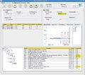
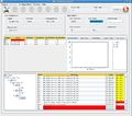
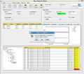
Images of RunControl Gui During Data Acquisition
CODA has a characteristic format for the data files that it outputs. These are exported from halldtrg5 to gluey via an NFS link. As mentioned earlier, this is for the dual reason of preserving halldtrg5's flash memory, but it also allows for easier access to the data files for analysis. In fact, the CODA output format is essentially useless on its own, and must be interpreted and converted to a useful format. This is accomplished via the Event Analyzer program, which is described below.
Analyzer
In order to be able to analyze the data collected by the halldtrg5 VME crate, it's necessary to convert the CODA output files to a more useful, user-friendly format. In this case, we have chosen to convert the CODA files to .root files.
The analyzer, written in C++, opens the CODA file, and is currently configured to read from an fADC and F1TDC (see above for descriptions). The CODA file consisting of events from a data run with these two components in operation. The analyzer was initially configured to read from two fADC's and one F1TDC, so this necessitated some reconfiguration. Since, as mentinoned before, I was relatively inexperienced with programming at the beginning of the semester, there was a relatively steep learning curve, as there are few comments and no documentation for the Event Analyzer file that was included with Halldtrg5, and this file was only intended to serve as an example. With the help of Alexander Somov from Jefferson Lab, I was able to make some sense of the analyzer, and use it to create .root files from my test set-up with the function generator.
I encountered a major problem at the end of the semester when I discovered that the set-up that I had been using was not exactly suitable for the testing that Dr. Jones and Alex Barnes had planned to do on the optical fibers. I had to incorporate an Event Recorder into the data acquisition run, by creating an mSQL database for CODA that included an Event Recorder. However, this lead to strange error messages when trying to initialize data runs, which I could resolve only by removing the Event Recorder from the database. This is not a feasible solution, since this prevents usable events from being recorded in the CODA output file. Without events, the Event Analyzer has nothing to export to the .root file. I plan to try to resolve this issue during the winter intersession. I have been speaking with Alex Somov some more regarding this, and hopefully he will be able to shed some light on how to fix this issue.


