Fiber QA Troubleshooting
Jump to navigation
Jump to search
Troubleshooting of the QA Procedure required many runs and a few weeks. The results of those runs were motivations for changes to the testing procedure including: modification to the pulser circuit, modification to the pulser power source, standardized methods of placing the fibers into the chimneys, and consideration of temperature in analyzing photon yield. The results of these preliminary tests can be found below:
- Ann Marie's Troubleshooting Tests before the pulser circuit was modified
- Liana's Troubleshooting Tests after the pulser circuit was modified
- Liana's Work Journal and Liana's Summer Wiki Page accompany her Troubleshooting tests which describes more in-depth the thought process and steps behind each run.
Fiber Class
We wanted to see if there was a correlation between painting/gluing and the photon yield of the fibers. We decided to place each fiber into a separate fiber class depending on the current state of the fiber. The fiber classes are as follows:
- SG - untouched fibers from Saint Gobain
- S - straightened but not fused
- F - straightened and fused
- B - bent and never painted
- P - painted
- .5P - half painted
- U - paint removed (unpainted)
Previous Procedures
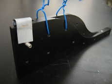
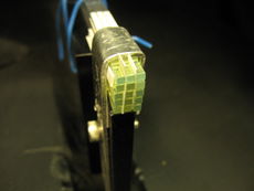
- Metal clamps and wires were previously used to secure the bundles of 15 to the fibers' popsicle sticks. We then graduated to using only one metal clamp over two 15-fiber bundles and two kapton strips per popsicle stick.
- We are currently working on making the paper spacings procedure easier.
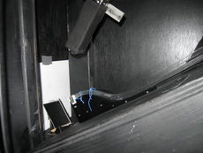
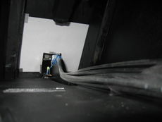
- The following photos were taken before the pulser circuit was fixed (added around June 16th) and before the pulser ran on a power supply. The pulser was modified to run on a power supply on July 3rd, 2014. You can see the results of this change on the "Scramble on Power Supply" page of the Fiber QA Troubleshooting Google Doc
- The initial procedure for paper spacing was to place paper under the kapton strips, but we later found that it caused too much of a gap between the scintillators. The paper spacers were then only placed at the beginning of the S-bend.
