Fiber Array Prototype and Mass Production
Purpose
The purpose of this page is to outline the steps taken to produce a working prototype of the fiber array. This page will be updated as more trials and tribulations occur so that future researchers working on this project will have a solid set of instruction. Most of the improvements on the fabrication techniques could not have been possible with out the work of Carl Nettleton and Sarah Lamb and their contribution is greatly appreciated.
Cleaving
Previously fiber bundles were cut using a fly cutter by Alan Chasse. The fly cutter would crack the cladding of the outside fibers and were considered to be "sacrificial" reducing efficiency by 64%. However, an end mill has been used in the last cutting attempts with extremely favorable results. At most two fibers have experienced outer cladding damage and even so the fibers will be usable after gluing and painting. This will greatly increase the mass production of multiple bundles and pictures of the fibers response to both the fly cutter and end mill will be posted soon.
After many end mill runs, the standard 1/4 inch two fluted mill has been replaced with a 1/4 inch four fluted bit. We are hoping that the bit will reduce outer cladding damage as a result of a smaller cutting area per flute. Also, a cold air chiller has been constructed by Jim McIntyre to reduce the surface temperature of the milled fibers. This will allow for higher milling rpms and ultimately higher quality fibers.
Polishing
I have spent the most of my time researching and perfecting the polishing techniques required to yield a fiber of final product quality. Stream lining the production process is the main focus of my efforts concerning the waveguides and scintillators and to do so I am exploring the following new techniques for polishing.
- By standardizing the sequence of sandpaper grit and manufacturer we can not only eliminate the variance between nailbrush companies, but we can also decrease the training time required for new students to learn the polishing techniques.
- Finer grit sandpaper ( 400, 600, 1500, and 2000 grit made by 3m) has just been brought in and I hope to post new pictures showing the quality of polish for each grade of paper for reference.
- After researching other experiments using scintillating tubes I found that Jefferson Laboratories uses a plastic polish for their fibers. We will soon test Novus Plastic Polish for its effectiveness in polishing the waveguides and scintillators. Below is a link to the Novus website as well as to the Jefferson Lab website where the information was found.
- http://www.novuspolish.com/
- www.jlab.org/~cecire/share/mparts.doc
These are polished fibers that were worked on for over an hour each. They were cut without using the fly cutter and so you can notice on the scintillating fiber a presence of outer cladding. These images will serve as a reference of comparison for when we begin using the Novus Plastic Polish.


Gluing
The first of many trial gluing sessions was completed this week (8/31-9/4) with favorable results. Only three of the eleven fibers broke after curing which is an increase from past attempts. This is attributed to the new gluing station that was designed earlier which allows the glue to stay out of contact with anything but the ends of the fibers. I plan on keeping notes on which of the eleven gluing channels produced successful fibers so that I can determine if there is a slight defect in the alignment of the two opposing channels.
Fiber Splicing
After completing the first 5x5 bundle it was clear that the optical epoxy was not going to offer the strength required for our setup. Turning to new ideas for joining fibers our group came across three alternatives to splicing the fibers together, they are as follows.
1) Research and design of a fiber splicing laser setup-
- Dr. Richard T. Jones has written a program that simulates the temperature field in an optical fiber that is being locally heated by a time-dependent external source.
- Using this program it is possible to predict how the polystyrene fibers will heat and cool depending on changes made to constants of the plastic, air flow, ambient temperature, and power of the laser used for heating.
- We can then find the optimum conditions which include a localized pulse of energy that does not heat the outer cladding past 200°C (boiling point of polymethylmethacrylate) and develop a splicing station of our own.
- Extensive research into the optical properties of polystyrene have been performed. Specifically, we need to know at what wavelengths polystyrene absorbs light most efficiently. The suppliers of the optical fibers has absorption information for wavelengths ranging from 400-800nm. To supplement this data we found two articles that each studied the spectral absorption of polystyrene. Fitting this information together we were able to obtain the following plot of how each wavelength penetrates until it reaches extinction.
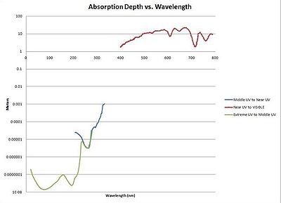
- Based on this information it is desirable to use a wavelength between 300-350nm because it allows for the light absorb a few tenths of a millimeter.
- The product spec sheet for the flash lamp used in the fuser (Wiko EMM/EKS-5) states that the bulb produces light with a blackbody temperature of 3400 K, which peaks in the near infrared.
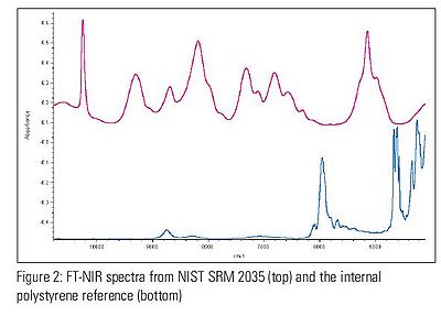
- The absorbance of polystyrene in the near infrared is reported in this technical note from Thermo Electric Corp, with this copy stored locally. The absorbance plotted below was measured for a sample of thickness 0.75 mm.
- For comparison, the absorption coefficient in the near infrared for borosilicate glass is reported in this article with this copy stored locally.


2) Michigan State University loan-
- Ron Richards, mechanical design specialist for the physics department at M.S.U. is loaning us a custom fiber splicer.
- Once received, the splicer must be refitted to splice square fibers as it is currently set up for round.
- Below is a photo taken of the MSU fiber splicer which was recently received.
 |
 |
- I have tested the alignment of the beam spot with respect to the center of the glass ferrules. In the photos shown below, it is clear that the lamp has maintained its alignment since its last use. Next, we wanted to ensure that the fibers were being held at the focus of the lamp. For our purposes it is important that the focus be set to the interior center of the joined fibers, reducing the intensity seen by the outer cladding. By comparing the sizes of the beam spots (intensity) measured in front, in line, and behind the glass ferrule it was possible to get a sense of the focal position with respect to the center of the fibers. The results show that the focus was too far forward and needed to be pushed back via the lamp mount. Once the lamp mount was readjusted the intensity was the greatest at the center.


- After numerous attempts I was finally able to fuse two fibers together using the MSU splicer. Replacing the standard glass ferrule (sent by MSU,having a circular diameter too small for our 2x2mm square fibers) with a glass cylinder with a 5mm diameter allowed us to form the fibers after they have been melted. As shown by the photos, the fibers take on the shape of the ferrule and the outer cladding is still in good condition. This is promising news and I have gone forward with contacting various glass manufacturers to obtain a proper ferrule. Also, it would be advantageous for our group to be able to produce glass ferrules on campus. I have begun cutting thin strips of glass in hopes that I will be able to produce my own ferrule. The results will be posted here shortly.


3) Outsource-
- Jim McIntyre has been in contact with several companies that specialize in precision plastic welding.
- Samples have been sent and are currently being tested to see which company has the ability to splice the fibers.
- Jim will update with results from said companies.
Painting
New improvements to the painting of the fibers includes the use of an airbrush for a finer distribution of paint. In the past, black spray paint from a can was used with relatively good results. If we are able to reduce the thickness of paint applied to each fiber however, we will reduce the chance of electrons falling into the gaps between fibers.
Assembly
more info coming soon