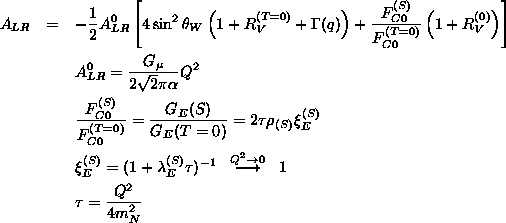
by measuring the parity-violating asymmetry in electron scattering at intermediate energies has been identified to be within the reach of experiments at CEBAF. In particular spin-0 isospin-0 nuclei in the low-A region are appropriate for these measurements because of the simple form nuclear current takes on in this case.
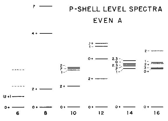
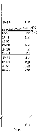
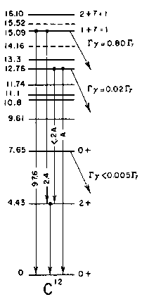
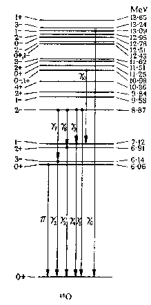
In order to separate elastic scattering from inelastic reactions, one would prefer a nucleus with the largest separation between the ground and the first excited states. Oxygen is the best candidate from this point of view, and also with regard to the cross section, which goes as Z2. Carbon is also interesting because it makes for a simple and compact target, with good heat tolerance properties. Nuclei heavier than 16O are less desirable from the point of view of low-lying excited states (see following figure). Also the ground states of these nuclides contain increasing admixtures of T>0 which complicate the interpretation of the data.
In this study I concentrate on three specific targets, 16O, 12C and 4He. Water is used for the oxygen target.
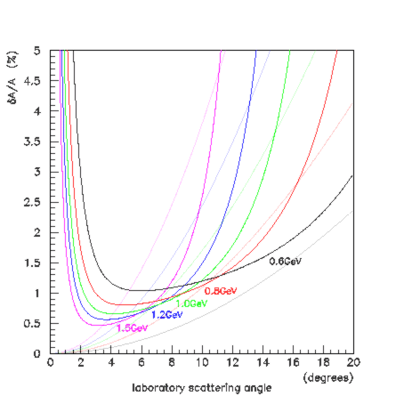
The strangeness radius is set to zero in the above calculation. The effect of a non-zero rho(s) will be shown in Fig. 3. In the following plot is shown the uncertainty in the measurement of the above asymmetry for an experiment performed under the following assumptions.
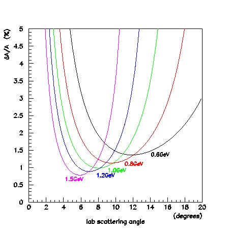
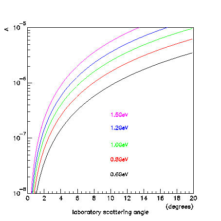
The statistical error alone reaches a minimum at a scattering angle of zero degrees for all beam energies, because the cross section rises faster than A2 is dropping as one approaches zero degrees. However this does not take into account the inherent difficulties involved with controlling beam conditions well enough to measure very small differences in experimental rates. Even if the rates are high enough that statistical accuracy is not a problem, one must also ensure that the magnitude of the asymmetry is large enough to measure under real experimental conditions. I take this into account by introducing into the experimental error a systematic uncertainty SA as follows.
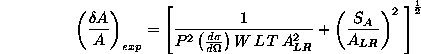
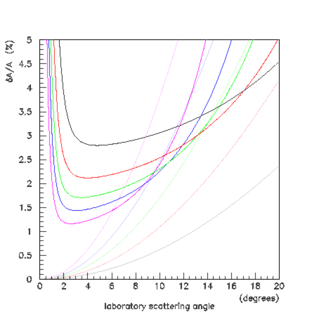
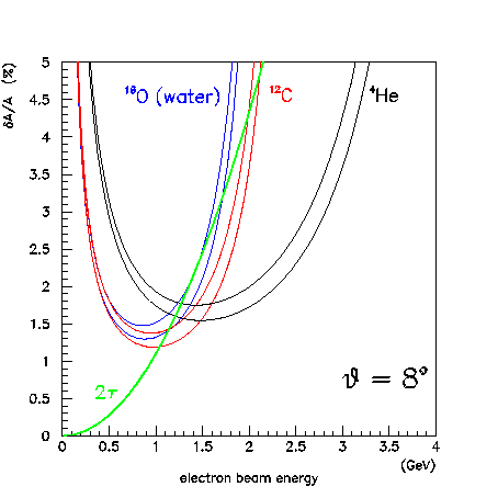
To obtain an idea of what might stand in the way of comparing a measured asymmetry with the Standard Model value, I plot below the percent uncertainty in A arising from the poorly known value of the strangeness radius of the nucleon rho(s). For this figure I have taken rho(s) to be uncertain by ±1. Right now I think this number is not known even that well. Comparing with Fig. 2 shows that parameter would need to be constrained before one could reach the level of measuring EW corrections.
Next Figs. 2 and 3 are shown overlayed. This shows that running at higher energy is relatively more sensitive to the strangeness form-factor. The best idea might be to divide the running between high energy to measure rho(s) and low energy where sensitivity to the residual uncertainty in rho(s) is the least.
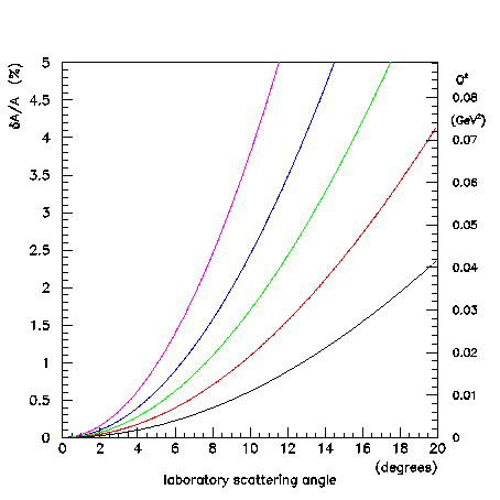
To see how these result depend on the systematic error on A I repeat the above figure for SA = 10-9. The optimum measurement angles move forward, as expected, and the experimental error on A for the conditions listed above improves somewhat. The colour coding is the same as in Figs. 1-4.
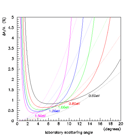
Now, for example, one might fix the spectrometer at 6° in the lab and split the running between 1.5GeV (to measure rho(s)) and 600MeV to measure EW corrections.
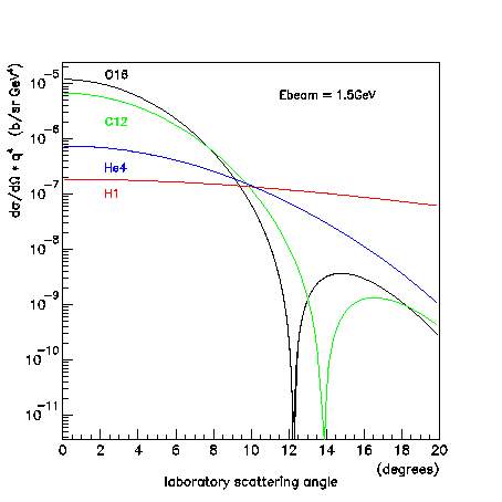
So far we have
only looked at 16O and with a water target there would
also be a contribution from hydrogen. A comparison of the cross
section for electron scattering from 16O and 1H
(among others) is shown next. The cross sections are multiplied
by q4 to facilitate the comparison at low angles.
The Standard Model asymmetry for the proton is shown next. There are contributions from the strange quarks involving both rho(s) and mu(s), but these are poorly known at present and have been left out of the calculation.
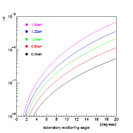
The precision with which the proton asymmetry can be measured under the above experimental conditions is shown in Fig. 8. A systematic error SA = 10-9 was assumed. This is not really relevant here because a water target would produce many more quasi-elastic than free proton events, so it is a different experiment. Fig. 8 also shows that the proton asymmetry is best measured at high energy, instead of around or below 1GeV, where one wants to run when measuring on a T=0 nucleus.
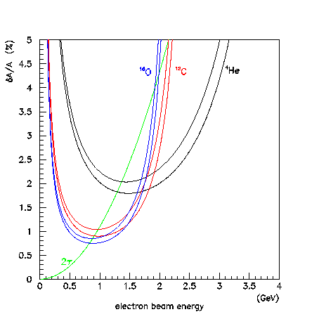
Of all 0+ targets, helium has the largest cross section from Q2=0.1GeV2 and greater. This makes it the best target for measuring rho(s). This measurement might be made at an intermediate value of Q2, for example with a forward-scattering experiment at a beam energy 2-3GeV, and then the value used in the interpretation of data taken below 1GeV where the contribution from the strangeness form-factor to the total asymmetry is smaller.
In addition to nuclear excited states, with a water target one must also be concerned at some level with separating out the contribution of scattering from the free protons. The following simplified picture of the focal plane serves to illustrate the kinematic separation between the two elastic peaks as a function of angle.
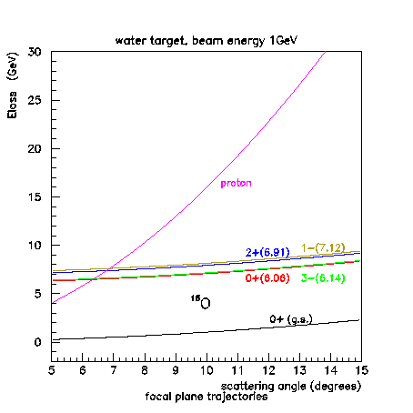
At a beam energy of 1GeV the proton lies beyond the excited nuclear levels for most of the accessible angular range, but at 600MeV the separation is less clear.
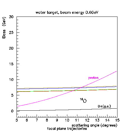
However at these low values of Q2 the cross section for 1H is a factor of 50 less than 16O (see Fig. 6) and the asymmetry of the proton is an order of magnitude less than for oxygen, so the effect is small and easily corrected for at low Q2. The same is not true at higher values of Q2, as one approaches the the diffraction minimum for 16O, where hydrogen would dominate the asymmetry. But there the kinematic separation is large. So the presence of hydrogen in water nowhere diminishes its effectiveness as an oxygen target.
The outcome of this preliminary comparison is that 16O in the form of water provides the best target for a precision measurement of the weak isoscalar charge of the nucleon. As was already shown by Musolf et.al. it is possible, within parameters reasonable for an experiment at CEBAF, to make a 1% measurement of this charge which would be competitive with the limits currently established by atomic parity-violation experiments. However there are still some experimental questions that have to be addressed for an experiment that would like to run at a luminosity of 1038cm-2s-1.
| target length (cm) | radiation length (cm) | target length (%rad.len.) | |
|---|---|---|---|
| water | 4.9 | 36.1 | 13.6 |
| carbon | 1.4 | 18.8 | 7.4 |
| helium (liquid) | 8.6 | 756 | 1.1 |
The two effects related to resolution that arise when considering targets as thick as 0.1X0 are external bremsstrahlung and multiple scattering in the target.
For the bremsstrahlung spectrum I take the following simplified formula, which has the correct infrared behaviour, the right average radiation rate (if x is measured in radiation lengths) and cuts off at the endpoint.
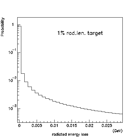
For a target of 0.1 radiation lengths or larger, as shown in the next figure, the first bin no longer contains the majority of the scattered beam.
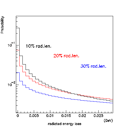
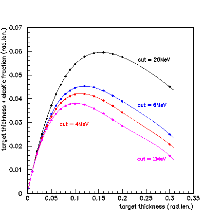
To apply these results to the problem at hand, I assume that a measurement at low angles involves a target geometry equivalent to the slices described above. This means that no matter where inside the target the primary scattering occurs, the electron must traverse the same amount of target material on the way to the detector. An exception to this assumption will be considered later in the case of an extended helium target. Integrating the probabilities in Figs. 14a-b up to Ecut gives the fraction of the elastic scattering events that enter into the measured elastic peak at the detector. This can be multiplied by the target thickness to yield an effective target thickness, that is, the equivalent amount of target that contributes to the measurable elastic cross section. This is shown for three different values of Ecut in the next figure. Note that these curves apply to any target material because thickness is measured in radiation lengths.
These results show
| cutoff (MeV) | max. eff. target thickness (% rad.len.) | phys. target thickness (cm) | eff. luminosity (1038cm-2s-1) | |
|---|---|---|---|---|
| 16O (water) | 6 | 4.5 | 4.3 | 0.33 |
| 12C (graphite) | 4 | 4.2 | 2.1 | 0.57 |
| 4He (liquid) | 20 | 5.9 | 113 | 5.4 |
| 4He (short) | 20 | 1.6 | 12.5 | 1.35 |
These are reasonable thicknesses for physical targets, except for the case of helium, which is highlighted in red in the table. There are several reasons why a target more than 1m long is a difficulty, not the least of which is the considerable amount of power that would have to be dissipated by the crygenics. This matter is taken up again in the next section. For the present purposes, I consider a 12.5cm (300W) target to be within the limits of what is practical, and proceed with the comparison on this basis. The parameters for such a target are shown in the last line of the above table.
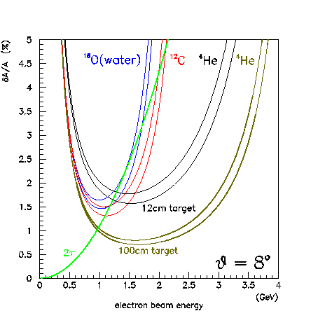
I now repeat the calculation of the experimental error on the measured asymmetry using the corrected values for the effective luminosity for each target. As before, the upper curve in each colour is the more important one, as it contains the cross section that one would actually measure.
Now all three targets are quite close to one another in the ultimate limits of their precision, although they differ somewhat in the kinematics where the optimum precision is reached. Carbon has edged out water by a small margin as the best target from the point of view of absolute precision.
Just as an exercise, I set aside questions of technical feasibility and spectrometer optics, and consider what the ultimate limits would be with a 1m helium target. This is shown in the next figure. Both this and the preceding figure are evaluated assuming a systematic error on A of 10-9.
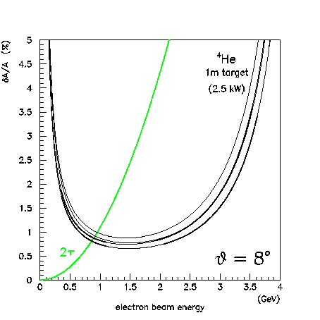
In the case of an extended target like this, it is no longer valid to consider that all of the electrons traverse the full thickness of the target. If the target were in the form of a tube of transverse dimensions only a few cm then the electrons would exit the target not far downstream of the primary vertex, giving the effect of a thinner target. They would, however, have to penetrate the walls of the target vessel at rather low angles, which would restore a part of the losses. For this study I assumed an aluminum target vessel with walls 300um thick, and recalculated the elastic yield taking into account the fact that a greater number of the detected elastic events come from the upstream region of the target, before the beam has begun to degrade due to radiation. The result is the lower pair of curves in Fig. 16, the upper (final) one of which largely overlaps with the lower curve of the "fat target" calculation.

At 1GeV with a target thickness of 0.1 rad.len. the r.m.s. angular spread from multiple scattering is 3.9mr, or about Ľ°. At 5° Q2 changes by 9% over 4mr, which implies the same rate of change for the asymmetry, and double for the cross section. At 8° the figure is 6% for the asymmetry. Multiple scattering in the interior of the accepted angular region does affect the result, which involves only the sum of all counts within the acceptance. Hence the only thing of concern with regard to multiple scattering is its effect on the acceptance near the edges, with the low-angle extreme being the most sensitive.
The implications for alignment would be that the overall spectrometer angle would have to be known to within ±0.1mr to ensure that geography would not contribute a significant amount to the total experimental error. With the proper placement and alignment of focal plane counters, it should not be a problem to reach the necessary precision with respect to angle, for a 1% measurement of the asymmetry.
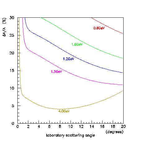
The net effect of the corrections considered above is to decrease the effective luminosity, and hence statistical accuracy, of the measurement. The question then arises whether a systematic precision at the level of 10-9 is still needed, or whether 10-8 is sufficient. The next figure shows the combination of the preceding two, but calculated for the case SA = 10-8.
There is small but not insignificant decrement in precision that comes with this additional systematic error. But the major issue is that in order to address the important physics issues with such an experiment we need to reach the 1% level. Besides hoping to surmount the difficulties involved in operating a 2.5kW liquid helium target, there is another way to increase the statistical precision of the measurement, which is to run for a longer period of time. Since the combination of 100uA and 70% polarization is already a challenge to achieve over the duration of a 1000hr experiment, it is probably not wise to count on signficant improvements in these values. In the next figure I show the uncertainty for a 2000hr experiment under the same conditions as have been studied so far and a systematic error of 10-8.
Finally, I repeat the calculation once again, substituting back a systematic error of 10-9. This probably comes close to what could reasonably be done in the near future at CEBAF.
I would like to highlight the potential of an experiment with
a water target. It is a 2000hr experiment with a 100uA
beam at 70% polarization with systematics on the asymmetry controlled
at the level of 10-9. It does not sound like an easy job.
The result would be a 1% measurement, that meets the criteria
put forward by Musolf et.al. for a
significant test of physics beyond the Standard Model. I think
that the importance of the issues involved warrant the kind of
effort that would be necessary to make an experiment of this type
a reality.
Appendix A: target heat dissipation
The ionization heating per unit length of a target is given by the
product IS in W/cm where current I is measured
in uA and stopping power S is measured in MeV/cm.
The total power for the optimized targets discussed in the text of this
report are shown in the following table.
| beam heating (W/cm) | target length (cm) | total power (W) | |
|---|---|---|---|
| 16O (water) | 200 | 3.6 | 720 |
| 12C (graphite) | 400 | 1.9 | 760 |
| 4He (liquid) | 24 | 113 | 2700 |
| 4He (short) | 24 | 12.5 | 300 |
A water target capable of dissipating 700W would have to be of the "waterfall" type. With the beam on the order of 1mm in diameter, the waterfall could be oriented so that it presents an edge to the beam. With this geometry the target could be quite thin in the transverse horizontal direction, which would reduce the effective amount of target seen by the average scattering electron, and hence reduce radiation losses somewhat. We would need to consult people with experience with waterfall targets to see whether such a scheme could be made to work.
The graphite target is the simplest of all. In this case most of the heat dissipation takes place by blackbody radiation. If 700W is too much for a stationary target one could construct a rotating target. There is no apparent difficulty with carbon.
With helium the amount of heating that could be handled by an
affordable cyrogenic system would be the limiting factor in what
could be done. If a 15cm target can be made to operate
successfully then several such targets could be arranged in series
up to the desired length, limited by the total cooling capacity
that could be put in place. Eventually there is also a limit
imposed by the resolution of the spectrometer viewing an extended
target, but at these forward angles I suspect that the cryogenic
limits will be reached first. In Appendix B is described work
that is presently underway to determine the experimental limits
imposed by the spectrometer optics at forward angles.
Appendix B: spectrometer resolution
The need for energy resolution at the level of a few MeV
restricts the choices to one or two spectrometers among what is on the
floor at CEBAF today. The following figure, clipped from the APS
news bulletin, shows the energy spectrum for electron scattering from carbon
at kinematics not far from what we are presently considering.
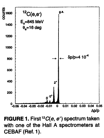
At UConn we are in the process of setting up a description of the HMS spectrometer in the program TRANSPORT which calculates the trajectories of charged particles through a sequence of magnetic elements. In this study we aim to determine what the trade-offs are between solid-angle, resolution, and far-forward acceptance for this spectrometer. Results from this study are expected by the end of the summer.
Richard Jones
University of Connecticut / Jefferson Lab