Spring 2011 Beam Test of
Active Collimator
Table of Contents
Tunnels for accessing in-hall resources off site
Initial scan for ActiveCollimator orientation
Accessing Hall B photon beam settings
New LabVIEW VI history file column headers:
Useful phone numbers:
Richard Jones - new shift started at midnight
Connected up to gummo (129.57.167.28) to confirm that it is still reachable. All 4 channels are set to 1012 gain and seem to show noise levels that are consistent with that gain setting. Igor noted that the noise levels on the outer wedges are smaller than what they were when the device was sitting on the floor near the entrance to the alcove earlier in the month. It is now mounted on top of the TAC. The plan is to use the TAC motion control system to scan the active collimator through the electron beam. Igor estimates that the active collimator axis is somewhat below the
height of the beam, within 2-3 cm. We will scan it horizontally through the beam and find the zero crossing in x, then go there and do a small vertical scan to find the symmetry point in y. Right now we have the problem that Igor is not able to access the EPICS variables that control the motion of the TAC. He believes that it may be a permissions problem. For the moment, the only way we have to move the TAC is by using the Hall B TAC motion control GUI, or remember the command-line commands that we used last time to make it carry out horizontal scans.
Action plan for the active collimator:
Igor: The LabView VI was running at 3s intervals taking 2s traces and appears to “choke” at times: not enough overhead time to save the data etc., evidently. It was affecting other services like VNC access. Increased interval to 4s. Let’s keep watch of the extra time necessary for the computer to keep up.
Richard: Here is a perl program that I found in the folder I made during the last active collimator test. It is a script that moves the TAC in x, writes the position and time values, waits for a fixed time interval, and then continues.
tac.pl:
#!/usr/bin/env perl
use Pezca;
use lib ("$ENV{APP}/fcup_gain/scripts/");
use LSF;
$| = 1;
$n = 0;
$date_time = localtime;
print "---------------- $date_time ----------------------------------\n";
($error,$tacx) = Pezca::GetDouble('tac_x.RBV');
($error,$tac) = Pezca::GetDouble('frwd_scalerS13b.VAL');
($error,$slm) = Pezca::GetDouble('scaler_calc2');
($error, $na_2c21) = Pezca::GetDouble('IPM2C21A.IENG');
($error, $na_2c24) = Pezca::GetDouble('IPM2C24A.IENG');
$slm_s = &round_off($slm);
$c21_s = &round_off($na_2c21);
$c24_s = &round_off($na_2c24);
$tac_s = &round_off($tac);
$tacx_s = &round_off($tacx);
while ($tacx<$tacx_s+5.) {
$tacx_p=$tacx+0.02;
# while($n<5){
# if ($na_2c21 < 5. || abs($c21_s - $na_2c21)>0.1*$c21_s ) {
## beam current does not match
# }
# else {
# $n++;
# sleep 2;
# }
# ($error,$slm) = Pezca::GetDouble('scaler_calc2');
# ($error, $na_2c21) = Pezca::GetDouble('IPM2C21A.IENG');
# ($error, $na_2c24) = Pezca::GetDouble('IPM2C24A.IENG');
# }
sleep 20;
$n=0;
$error = Pezca::PutDouble("tac_x",$tacx_p);
($error,$tacx) = Pezca::GetDouble('tac_x.RBV');
$tacx_a = &round_off($tacx);
($error,$tac) = Pezca::GetDouble('frwd_scalerS13b.VAL');
$tac_a = &round_off($tac);
$date_time = localtime;
print "$date_time $tacx_a $tac_a \n";
}
sub round_off {
my ($x) = @_;
$x = int(1000.*$x)/1000.;
}
The question came up, what is the variable above called “slm”. Franz suggests it is a “synchrotron radiation light monitor”, a secondary way to monitor the beam current. According to Franz, the above script is expected to work on machine clon01, username “clasrun”. I [Richard] used it back during the April/May 2007 test run, presumably from that machine, but Igor and Hovannes would prefer to get the labview control GUI working, and let us do everything from gummo. I agree that this would be preferable, provided that it does not take too much time.
9:40am
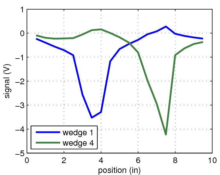
Moving active collimator: +6.49, +0.1 (from 0,0; all TAC coordinates in inches). Sweeping the active collimator horizontally across the beam, with the vertical coordinate left fixed at the parked height, shows a significant displacement only in the fourth octant. Viewed from the front, this is the right-most. Some momentary oscillation is seen in the first octant momentarily as it sweeps through the beam, but it does not show the large current (5V) seen in the fourth octant. The two central octants do not show any measureable response during the sweep, suggesting that the beam is either above or below the height of the central aperture.
Beam remains steady since last night, beam current is fluctuating between 7.5 and 10.5 nA. Effort this morning remains focused on getting the labview program to work that is designed to move the TAC by writing to EPICS variables controlling the x and y displacements. Igor and Hovannes are working together on the problem.
How to tunnel into the hall for Remote Desktop access to Windows PC’s.
How to tunnel access to a web server inside the Hall for access from an offsite browser.
Initial scan in the x direction at the default y=0.1”
This indicated the center of the beam was aligned with the collimator axis at around x=5.5”. A closer search in that area showed roughly comparable inner wedge currents at 5.4”. Based on that, the x offset was fixed at 5.4” and a scan in y was performed.
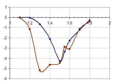
These data were recorded in the directory: OrientationScan-3-26-2011 run1. The results are shown by the two series at the right, blue=wedge 2, brown=wedge 3.
Center appears to be at 1.4cm: this is the value set into Hall B GUI for subsequent scans
During a preliminary, rough y-scan, where the beam likely went solidly through the needles of wedge 2, the signal exceeded 10V at maximum gain.
First menu window, “clas_epics” in the descriptions below is accessed with “clas_epics” command from clonXX machines.
The current choice will be highlights and/or the “motor position” will be shown to be compared to the listed location of the retractable element.
This is the first horizontal scan: HorizontalScans-3-26-2011/run1
Scan range was x=0.0 to x=11.0 in., y=1.4 in.
The settings of the scan GUI are as follows:
Scan was aborted at x=6.5 in. when beam trip paused the scan and was unable to recover. Igor is looking into the code to fix this.
Run 2: HorizontalScans-3-26-2011/run2
We are doing a re-run with the same values as run 1. Igor has changed the code so that the scan resumes after the beam stops and resumes.
Run 3: HorizontalScans-3-26-2011/run3
Values that have changed:
Run 4: HorizontalScans-3-26-2011/run4
Values that have changed:
Run 5: HorizontalScans-3-26-2011/run5
Values that have changed:
Run 6: HorizontalScans-3-26-2011/run6
Igor suggested that we do a more precise run around the center of the beam. The scan range is concentrated around x=5.4 (the calculated center of the beam) and the step size has been reduced. Values that have changed: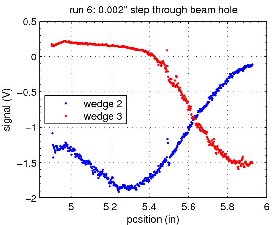
At this point the collimator was moved down by 0.02 in. to y=1.38 in. by a technician at Jlab.
Run 7: HorizontalScans-3-26-2011/run7
Values that have changed:
Run 8: HorizontalScans-3-26-2011/run8
Values that have changed:
Run 0: HorizontalScans-3-27-2011/run0
To follow up on the fine-step run6 of previous day, I [Igor] am doing a fine, long-trace scan around the beam hole. I want to be able to get a stability analysis by frequency so long time windows are important to avoid smearing low frequency components (indeed, the scatter of DC in run6 probably comes from the short, 1s, traces gathered)
Scan:
Run 2: HorizontalScans-3-27-2011/run2
Long-time-window step through the whole collimator. Parameters:
Run 3: HorizontalScans-3-27-2011/run3
Run 4: HorizontalScans-3-27-2011/run4
I (Ann Marie) had made a mistake with the timing of the moving of the collimator so am doing a new run with the changed values as follows:
Run 5: HorizontalScans-3-27-2011/run5
Run 6: HorizontalScans-3-27-2011/run6
aborted at 5.57 inches due to channel two saturating.
Run7: HorizontalScans-3-27-2011/run7
To determine the exact center of the beam we will do a fine scan. From x=5.6 to x=5.7 with step size (x)=.01 inches. We will then look in the log book to determine where the center of the beam is.
Run8: HorizontalScans-3-27-2011/run8 trc_1-15
Run at the center position determined from run7 (x=5.6465).
Run8: HorizontalScans-3-27-2011/run8 trc_16-44
Analysis of Run6, Run7, and Run8 from 3-26-2011
Horizontal scans from Saturday 3/26/2011
Run # | trace len. (s) | interval (s) | time to move (s) | step size (in) | x bounds (in) | y pos. (in) | gain V/A | ADC range (V) | Comments |
1 | 1.0 | 5.0 | 1.0 | 0.1 | 0.0-11.0 | 1.4 | 10-9 | +/- 5 .0 | scan stopped at x=6.5 in. |
2 | 1.0 | 5.0 | 1.0 | 0.1 | 0.0-11.0 | 1.4 | 10-9 | +/- 5.0 | code fixed for this run |
3 | 1.0 | 5.0 | 1.0 | 0.1 | 0.0-11.0 | 1.4 | 10-10 | +/- 10.0 | |
4 | 1.0 | 5.0 | 1.0 | 0.1 | 0.0-11.0 | 1.4 | 10-10 | +/- 5.0 | |
5 | 1.0 | 5.0 | 1.0 | 0.02 | 0.0-11.0 | 1.4 | 10-10 | +/- 5.0 | |
6 | 1.0 | 5.0 | 1.0 | 0.002 | 4.9-5.9 | 1.4 | 10-10 | +/- 5.0 | concentrated on center |
7 | 1.0 | 5.0 | 1.0 | 0.01 | 0.0-11.0 | 1.38 | 10-10 | +/- 5.0 | lowered collimator |
8 | 1.0 | 5.0 | 1.0 | 0.01 | 0-11.0 | 1.42 | 10-10 | +/- 5.0 | raised collimator |
Horizontal scans from Sunday 3/26/2011
Run # | trace len. (s) | interval (s) | time to move (s) | step size (in) | x bounds (in) | y pos. (in) | gain V/A | ADC range (V) | comments |
1 | 5.0 | 3.0 | 0.001 | 5.5-5.7 | 1.4 | 10-11 | +/- 10.0 | called /run1 | |
2 | 5.0 | 3.0 | 0.01 | 2.0-9.5 | 1.4 | var. | +/- 10.0 | gain changed as needed | |
3 | 5.0 | 3.0 | 0.01 | 2.0-9.0 | 1.4 | 10-10 | var. | ADC changed as needed. Not sure about x | |
4 | 5.0 | 10.0 | 3.0 | 0.01 | 5.5-5.7 | 1.4 | 10-10 | var. | ADC changed as needed |
5 | 10.0 | 16.0 | 5.0 | 0.01 | 5.5-5.7 | 1.4 | 10-10 | var. | ADC changed as needed |
6 | 10.0 | 16.0 | 5.0 | 0.01 | 4.9-5.9 | 1.4 | 10-10 | var. | ADC changed as needed |
Run0: HorizontalScans-3-28-2011
We are attempting to find the proper y orientation. Run0 is a sweep of the center at the current y-position of y=1.40in
Run1: HorizontalScans-3-28-2011 -- started at 07:55
Run 2: HorizontalScans-3-28-2011 started at 1840
Run 3: HorizontalScans-3-28-2011
… a few more scans under the same conditions, finer step size for good measure.
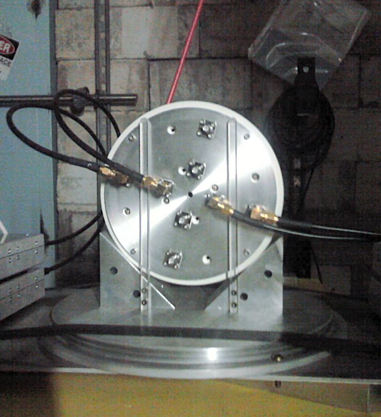
Igor: had access to the whole late Monday evening. Checked on collimator - the “top” marking looked fairly well oriented. Now, the cables on the right hand side (wedges 1 & 2) were tilted up to stay clear of beam scanning in x direction, but they were tilted to close to 45deg. The connectors, have fairly solid copper cubes for elbows and the beam may gave showered on the corner of the connector to wedge 2. I thought it would be useful to tilt the cables to a more modest angle, the way it is on the right so that subsequent scans are cleaner. Either way this would teach us something. The adjacent photo shows the adjusted layout.
Richard Jones, Mar. 29 06:00
I set up jobs to copy the data files from the hard drive on gummo back to the cluster. My intention is to collect all of the trace files that go with a run summary file (runN) into a tarball and store them as runN_trc.tgz in the same directory. These can then be archived on dcache.