Parasitic Beam Request 3-2007
Richard Jones
March 22, 2007
Overview
A prototype of the active front-end of the photon beam collimator
being built for Hall D has been assembled and bench-tested at the
University of Connecticut
[1,2,3].
The detector senses the position of the photon beam by measuring the
current produced by knock-on electrons generated in the early stages
of an electromagnetic shower. An segmented tungsten block partitioned
in both radius and azimuth doubles as the shower material and the cathode.
The tungsten wedges are positioned just upstream of the entrance face of
the primary collimator, which serves as the anode of the detector circuit.
A hole through the center of the tungsten plates allows the collimated
photon beam to pass unattenuated. No bias voltage is applied to the
detector; the current is driven by the shower energy when the beam is on.
A difference between the measured currents in opposite sectors is the
signal of beam misalignment.
According to Monte Carlo simulations, the currents in the inner sectors
at full operating intensity in Hall D are on the order of 1 nA. However
to be useful during initial running at reduced intensities it is essential
that the device be sensitive to photon beam position at currents as low as
30 nA, where the expected currents are on the order of 10 pA. Using
current-sensitive preamplifiers with a transimpedance gain of
1011 Ω, the device has been shown on the bench to
be sensitive to currents on the order of 0.1 pA with a bandwidth of
100 Hz.
The primary collimator prototype has been assembled and tested at the
University of Connecticut with two opposing tungsten quadrants installed.
Two high-gain current preamplifiers have been interfaced to a PC using a
PCI adc card and read out using the Labview data acquisition package.
The proposal requests permission to install the detector and in the Hall
B alcove and monitor the response of the detector to the g13 tagged
bremsstrahlung beam in parasitic mode.
Physical description
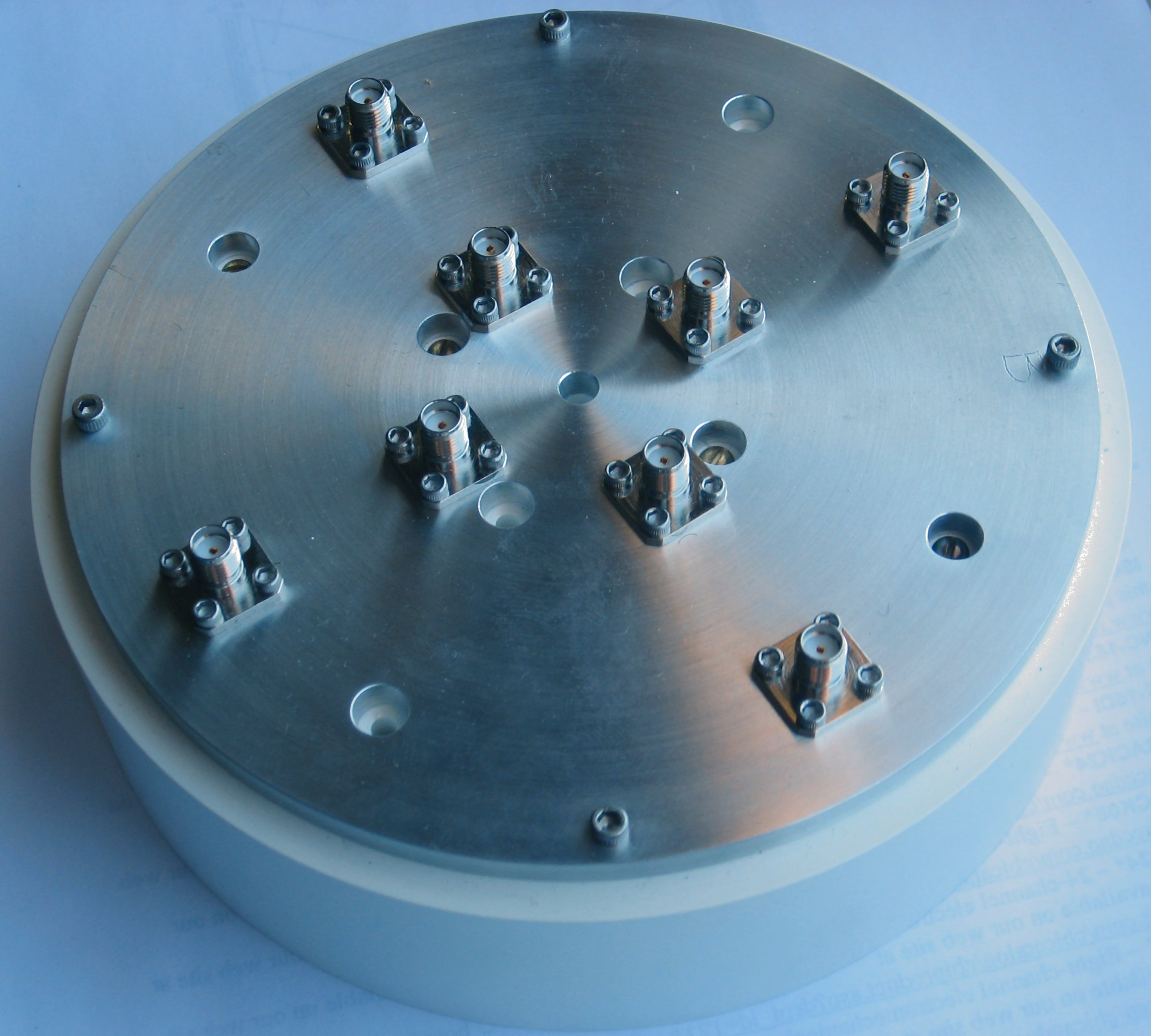 The active collimator is a disk of 14.72 cm diameter 4.2 cm
thick. There is a clearance hole of 5 mm diameter through the central
axis for the passage of the central core of the photon beam. Normally the
primary tungsten collimator would sit directly behind the detector, but
that object does not currently exist. There is an aluminum casing around
the active collimator elements that is sufficiently thick to provide the
return path for the current loop, so the lack of additional material behind
the detector to stop the knock-ons and return them through a low-impedance
path to ground is not expected to make any observable difference.
The active collimator is a disk of 14.72 cm diameter 4.2 cm
thick. There is a clearance hole of 5 mm diameter through the central
axis for the passage of the central core of the photon beam. Normally the
primary tungsten collimator would sit directly behind the detector, but
that object does not currently exist. There is an aluminum casing around
the active collimator elements that is sufficiently thick to provide the
return path for the current loop, so the lack of additional material behind
the detector to stop the knock-ons and return them through a low-impedance
path to ground is not expected to make any observable difference.
For the beam test, the collimator will rest on its outer insulating
case. The outer surface of the case has been machined to a cylinder with
an axis on the center of the clearance hole to a precision of
±125 microns. Only two electronics channels are currently
available for the readout. Two opposing sectors along the horizontal
axis will be tested. The detector will be mounted on a table equipped
with a horizontal translation stage. A translation stage will be
set up with remote control between limit switches which allow
±5 cm of motion in the horizontal direction transverse to
the beam. The detector will be held fixed on the translation stage
by a pair of wedges under its base that prevent it from rolling.
Goals
- Check the Monte Carlo prediction for the number of knock-on
electrons per gamma shower in the tungsten.
- Check the noise floor and the EMI pickup at 60Hz and its harmonics
in the experimental hall under actual running conditions.
Resource request
- Space in the alcove
A table is needed along the beam axis in the Hall B alcove that reaches
to within 6-10 inches of beam height. The table must be sufficiently
large to hold the translation stage. Shims under the translation stage
or under the detector will be used to raise the height of the center of
the detector to beam height. Two coaxial cables of approximately 50 cm
length are attached to the detector and connect to preamplifiers. The
preamplfiers will be secured to the table or translation stage in a way
that leaves sufficient slack for the 10 cm of horizontal travel.
Within 10 feet of the table space is needed for a PC (Dell tower)
and preamplifier power supply. The PC provides digital controls to
the preamplifiers and acquires the data. A fast-ethernet connection to
the PC is required. The PC has no screen or keyboard because it is
remotely controlled using VNC. Power for the PC and power supply is
required.
- Help with installation
The table will have to be installed in the alcove under the photon beam
axis and leveled. The translation stage will then be installed on the
table and raised to the height of approximately 8 cm below the
beam line. The collimator will then be placed on the table and secured
against rolling. The readout cables will then be attached and the
detector oriented with the measurement axis within a few degrees of the
horizontal and the face approximately perpendicular to the beam axis,
also to within a few degrees. With the translation stage in a reference
position, we then want to determine the position of the nominal photon
beam axis with a precision of ±1 mm. The data acquisition
system will then be configured and checked out. Assuming that all of the
required materials are obtained in advance, the total time anticipated for
this installation task is one half-day. We also need to consult with
Radcon regarding the protocol for removing this device before we install
it on the beam line because we want to be able to take it offsite later
for further prototype development.
- Duration of the test
This device is completely passive, having no bias voltage applied to
any of its components. Our preference would be that it remain in place
until the end of the g13 run period and be able to take data
whenever beam is in the hall. This will enable the student who is
responsible for the data acquisition software to be looking at the data
and further develop the software to help answer questions that arise.
The data acquisition system is entirely decoupled from what currently
exists in the hall. Control of the translation stage is a separate
issue; that control takes place through EPICS and should be under the
oversight of the CLAS shift operator.
- Impact on g13
No modifications to the photon beamline or shielding are required for
this test, other than the placement of the detector in the beam at the
back of the hall. There are no outstanding safety issues with this device
because it is entirely passive. Killing the power to the hall in case of
an emergency would have no impact other than to abruptly shut down the PC.
The internal detector tolerances allow for differential expansion within
the temperature range -20° to +50°C. The table should provide
minimal obstruction to the passage to the back of the alcove. A 24/7
telephone number will be available in the counting room in case questions
arise regarding this apparatus. One of us will take responsibility for
the timely check-out and removal of the detector and associated hardware
from the hall at the end of the test.
Further tests
It is anticipated that follow-up beam tests of the active collimator
will be needed as soon as more of the detector is instrumented. Before
a proposal for further tests in Hall B is submitted, the results of the
parasitic tests will be written up in a report. This report will be
posted on the GlueX docdb portal and a copy distributed to the g13
spokesman and the Hall B leader.
References
- C. Gauthier and R.T. Jones,
"Simulation of Shielding Options for an Active Collimator",
Gluex-doc-60, 2003.
- C. Gauthier and R.T. Jones,
"Simulation of a Position-Sensitive Tungsten Pin-Cushion Detector for GlueX",
Gluex-doc-244, 2003.
- I. Senderovich and R.T. Jones,
"Assembly and Bench Tests of an Active Collimator",
GlueX-doc-759, 2007.