Richard Jones, University of Connecticut
draft 1.1, March 22, 2006
Photon Tagger and Beam Line Working Group,
GlueX Collaboration

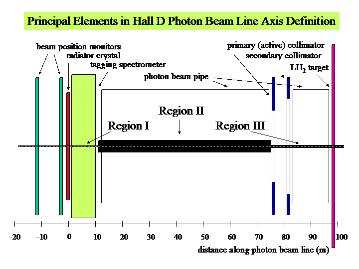
The above figure shows the principal elements that must be aligned relative to the beam axis. The nominal beam axis is represented by a horizontal dashed line through the center of the figure. The heavy black lines that lie on top of the nominal axis are supposed to symbolize the tolerance with which beam line elements must be located in the transverse plane relative to the nominal axis. The numerical values for these tolerances are given below. One of the uses for these numbers is to specify how accurately the site survey must be able to locate the nominal beam axis for alignment purposes. It may be useful for other reasons to know the absolute coordinates to better accuracy than required for the photon beam alignment; these numbers represent an upper bound on the survey uncertainty.
Numerical tolerances on the transverse alignment of all systems shown in the above figure are given in the table below. Only simple translations are considered in relating the coordinate systems in different regions. Of course angular misalignments between the two systems are also very important. For an explanation of how angles are effectively included in the way the numbers are specified in the columns labeled "external tolerances" in the table, see note [1] below.
Note that these alignment requirements are allowed in some cases to be less restrictive than the requirements on beam positioning accuracy during experimental running. The most critical parameter is the position of the photon beam spot on the face of the primary collimator relative to the collimator axis, which must be 0 ± 0.2 mm. That requirement is met by use of an active photon beam collimator that senses the photon beam position and feeds back that information in real time to electron beam correctors upstream of the radiator position. The range of the correctors will be sufficient to steer the photon spot anywhere within a circular zone of radius no less than 20 mm of the null electron beam axis determined by the zeros of the beam position monitors (BPM's). If the BPM's and collimator are misaligned at the outer limits permitted in the table below, the null electron beam axis will miss the collimator center by 8 mm, well within the range of the correctors. The BPM's are assumed to be 10 m apart.
The effects of these allowances on the positioning accuracy of the electron beam spot at the radiator depends on how far upstream of the radiator the correctors are located. They must be upstream of the BPM's, which sets a lower bound of 10 m. Assuming a distance of 15 m, a displacement of 8 mm at the collimator becomes 1.3 mm at the radiator. This is about the maximum amount of freedom that one has in the beam position at the radiator in the y direction relative to the mid-plane of the tagging spectrometer. Therefore it is the restricted range of allowed motion of the electron beam in y at the radiator that sets the bound for the region III tolerances. The maximum displacement of the photon beam spot on the experimental hydrogen target allowed by the tolerances in the table is 1.2 mm in x and y, which is acceptable.
| internal tolerance | external tolerance | external reference | |||
|---|---|---|---|---|---|
| x (mm) | y (mm) | x (mm) | y (mm) | ||
| Region I | 0.2 | 0.2 | 0.5 | 0.5 | accelerator |
| Region II | 20 | 20 | 25 | 25 | Region I |
| Region III | 0.5 | 0.5 | 2 | 2 | Region I |
The tolerances on Region II alignment have deliberately been relaxed to allow for a beam pipe with loose positioning requirements. It assumes a beam pipe of 75 mm radius (6-inch pipe), large enough to accommodate 45 mm of misalignment of sections of the beam pipe (relative to the axis defined in Region I) and a circular keep-out zone of diameter 60 mm for freedom to steer the photon beam during the beam alignment process.
This material is based upon work supported by the National Science Foundation under Grant No. 0901016.